
In this post I will demonstrate volume rendering of 3D image data in VTK. This will include loading and casting a segmented label-field, defining appropriate color and opacity transfer functions, setting volume properties, and performing volume rendering with different VTK classes, e.g., ray-casting or texture-mapping, which are implemented either on the CPU or GPU.
Introduction
Background
Some of you might have read my previous post about surface extraction. Well in that post we performed an automatic segmentation of the bone-structures in a CT dataset and extracted a 3D surface depicting those structures. You might remember that same skull model was used later in my post about ray-casting.
Well the ‘problem’ with those surface models is that they’re exactly that, surfaces! Essentially they’re 2D surfaces arranged in a 3D space but they’re entirely hollow. Take a look at the figure below.
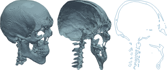
As you can see, what we’ve got here is two surfaces defining a ‘pseudo-volume’ but there’s nothing in them which becomes obvious when we clip/slice through them. The clipping and slicing in the above figure was performed in ParaView using the STL model of the skull which was used in the previous post about ray-casting.
However, it is often the case that we want to visualize the entirety of a 3D volume, i.e., all the data that lies beneath the surface (yes, that was another one of my puns). Well, in that case we need to resort to a technique aptly termed ‘volume rendering’.
Per the VTK User’s Guide, “volume rendering is a term used to describe a rendering process applied to 3D data where information exists throughout a 3D space instead of simply on 2D surfaces defined in 3D space”. Now, volume rendering is a inordinately popular topic in graphics and visualization. As a result, its one of the few topics in VTK that’s surprisingly well documented. Due to its popularity its also one of the actively developed areas in VTK (check out this post on VTK volume rendering updates on the Kitware blog). Should you want to learn more about volume rendering, and there’s lots to learn, I’ve arrayed a number of resource links at the end of this post.
The Dataset: Brain Atlas
Today’s dataset comes from a project entitled ‘Multi-modality MRI-based Atlas of the Brain’ by Halle et al. and it is currently available in the Publication Database hosted by Harvard’s Surgical Planning Laboratory (SPL). In a nutshell, this project provides us with a very nicely segmented label-field of the human brain with something like 150 distinguishable brain structures, along with the original medical image data.
What I did was download this version of the atlas, which I then relabeled, resampled to make the resulting renderings prettier, and boiled it down to a compressed .mha file. Unlike the MHD format, which was discussed in the previous post about multi-modal segmentation, this .mha file contains both the header and binary image data within the same file. In addition, I modified the accompanying color-file, which is essentially a CSV file listing every index in the label-field along with the name of the represented brain structure and a recommended RGB color.
What you need to do is download today’s dataset, and extract the contents of the .zip file alongside today’s notebook.
Summary
The purpose of today’s post isn’t to teach you everything there’s to know about volume rendering in VTK. Volume rendering is actually a pretty immense topic and even if I knew everything there was to teach, which I don’t, it would take a book-chapter-sized post to do so.
What I intend to do today is equip you with the tools and knowhow to perform volume rendering of your own image data, thus giving you another view into your data. Therefore, this post is merely meant as an introduction.
I will start by loading and casting the label-field in today’s dataset to make it compatible with the volume-mapping classes I’ll be using. Then I’ll be defining color and opacity transfer functions, the most important part of the entire volume rendering process since these functions define how the resulting rendering is going to look. Once these are defined, I’ll demonstrate volume rendering with some of the different volume mapping classes offered by VTK and show you their results.
Volume Rendering with Python and VTK
Should you want to try out the presented code yourself then you should download today’s notebook and dataset, which should be extracted alongside the notebook.
Imports
As always, we’ll be starting with the imports:
import os
import numpy
import vtk
I know I’ve said in pretty much every post pertaining to VTK but if you don’t have a working installation of Python with VTK then do yourselves a favor and use Anaconda Python (check this early post on it).
Helper-Functions
The following ‘helper-functions’ are defined at the beginning of today’s notebook and used throughout:
vtk_show(renderer, width=400, height=300): This function allows me to pass avtkRendererobject and get a PNG image output of that render, compatible with the IPython Notebook cell output. This code was presented in this past post about VTK integration with an IPython Notebook.createDummyRenderer(): A very simple function, that just creates avtkRendererobject, sets some basic properties, and configures the camera for this post’s rendering purposes. As we’ll be rendering several different scenes I thought it’d be simpler to just create a new renderer/scene for every case rather than removing/adding actors all the time, thus making each rendering independent from its preceding ones. The code included in this function has been previously detailed in this previous post about ray-tracing and this previous post about surface extraction.l2n = lambda l: numpy.array(l)andn2l = lambda n: list(n): Two simplelambdafunctions meant to quickly convert alistortupleto anumpy.ndarrayand vice-versa. These function were first used in this past post about ray-tracing with VTK.
Options
Near the beginning of today’s notebook we’ll define a few options to keep the rest of the notebook ‘clean’ and allow you to make direct changes without perusing/amending the entire notebook.
# Path to the .mha file
filenameSegmentation = "./nac_brain_atlas/brain_segmentation.mha"

# Path to colorfile.txt
filenameColorfile = "./nac_brain_atlas/colorfile.txt"

# Opacity of the different volumes (between 0.0 and 1.0)
volOpacityDef = 0.25
The two options filenameSegmentation and filenameColorfile, simply show the location of the .mha file and the .txt ‘colorfile’ in today’s dataset, the contents of which you should have already extracted alongside today’s notebook.
The third option, volOpacityDef, comes into play later when we’re defining the opacity transfer-function for the volume-mappers but all you need to know now, is that this will be the baseline opacity of all rendered brain-structures.
Image-Data Input
Firstly, we obviously need to load the label-field under the provided .mha file. VTK has inherent support for (un)compressed MetaImage in either the .mhd or .mha formats. Reading them is performed through the vtkMetaImageReader class. Here’s how its done:
reader = vtk.vtkMetaImageReader()
reader.SetFileName(filenameSegmentation)

castFilter = vtk.vtkImageCast()
castFilter.SetInputConnection(reader.GetOutputPort())
castFilter.SetOutputScalarTypeToUnsignedShort()
castFilter.Update()

imdataBrainSeg = castFilter.GetOutput()
We initially create a new vtkMetaImageReader object under reader and set the filename from which to read, which was defined as filenameSegmentation in the Options. By itself, this class would read the properties of the image stored in the file’s header as well as the image data itself and create a new vtkImageData containing both. So far so good.
Then, a little trickery :). As you’ll see later on, one of the classes we’ll be using for volume-rendering will be the vtkVolumeRayCastMapper class. While you won’t see it anywhere in the class’ documentation, this class only works with unsigned char and unsigned short data types and chances are, and were in our case, that your data isn’t in that type. Therefore, we need to cast it :).
Thankfully, casting the data type of a vtkImageData object is super simple, if you know where to look. What we do is create a new vtkImageCast object under castFilter and connect its input to the reader output thus feeding it the image.
I’ve talked about the VTK pipeline in previous posts but I think this is a good place for a long-winded reminder. As you can see, we haven’t yet called the
Updatemethod in thereaderobject. Therefore, at this point we haven’t actually read the image data but merely prepared thereaderto do so. The idea is to read in that data and immediately cast it rather than reading it, keeping a unnecessary copy of the un-cast image, and then another copy of the cast one. That’s why we used theSetInputConnectionmethod of thecastFilterand theGetOutputPortof thereader. Once we callUpdateon thecastFilterit will ask thereadertoUpdatehimself, thus reading the data, and pass a pointer to its newly acquired output, i.e., the image, on which it will operate and cast.
The key then, is calling the appropriate method to set the desired data type of our output image. In our case we want the output image to be of unsigned short type so we call the SetOutputScalarTypeToUnsignedShort method. However, we could’ve set it to any type such as float through SetOutputScalarTypeToFloat or signed int through SetOutputScalarTypeToInt. Check the vtkImageData docs to see the names of all such methods.
Lastly, we just call Update on the castFilter which subsequently calls Update on reader, gets the ‘original’ image data, and casts it to a type of unsigned short. We retrieve that data through GetOutput and store it under imdataBrainSeg.
Prep-work
Before we actually start volume rendering we need to do some prep-work. In fact this preparation is the most important part of volume rendering and what defines how good your subsequent renderings will look. What we’ll be doing now is defining the transfer-functions and volume properties.
Transfer functions
The appearance of any volume rendering pretty much boils down to defining transfer functions. These transfer functions tell the volume mapper what color and opacity to give to every pixel in the output.
Color function
Firstly, we need to define a color transfer function, to which I’ll be referring as ‘color function’ from now on. This needs to be an instance of the vtkColorTransferFunction class and acts as a map of scalar pixel values to a given RBG color.
When dealing with label-fields with a limited number of different labels, its common to assign a unique color to each label, thus distinguishing the different tissue structures in the rendering. That’s where the color-file in today’s dataset comes in. Color-files or tissue-lists are very common in segmentations. Typically stored in a CSV format, they’re simply a list where each label index is mapped to the tissue name and optionally an RGB color. The color-file in this dataset follows a very simple format like this:
0,background,0,0,0
1,white_matter_of_left_cerebral_hemisphere,245,245,245
2,left_lateral_ventricle,88,106,215
3,temporal_horn_of_left_lateral_ventricle,88,106,215
...
The first integer is the label index, the same way it appears within the image data. That is followed by the name of that tissue and three integer values between 0 and 255 for the RGB color.
While we could simply read-in that data with the readlines method of Python’s built-in file class let’s do so using the csv Python package instead:
import csv
fid = open(filenameColorfile, "r")
reader = csv.reader(fid)

dictRGB = {}
for line in reader:
    dictRGB[int(line[0])] = [float(line[2])/255.0,
                             float(line[3])/255.0,
                             float(line[4])/255.0]
fid.close()
The above snippet is really very simple and warrants very little explanation. All we do is loop through each entry read from the colorfile and create a dictionary dictRGB where the index-label acts as the key and the value is a list with the RGB color assigned to that tissue.
Note that we’re skipping the tissue name and more importantly that we’re ‘normalizing’ the color values to a value between 0.0 and 1.0 as this is the range that VTK expects. At this point we’re ready to define the ‘color function’ in VTK:
funcColor = vtk.vtkColorTransferFunction()

for idx in dictRGB.keys():
    funcColor.AddRGBPoint(idx,
                          dictRGB[idx][0],
                          dictRGB[idx][1],
                          dictRGB[idx][2])
As you can see we first create a new vtkColorTransferFunction under funcColor, which allows us to create that label index-color map we discussed previously. Then we simply loop through all keys in the dictRGB dictionary created prior, i.e., all label indices, and use the AddRGBPoint method to add a point with that label index and the matching RGB color.
The
vtkColorTransferFunctionis a function which includes interpolation routines in order to define in-between colors should these be required by the volume mapper. Thus, while we’ve defined given colors for given label indices, this value can return in-between colors as well by interpolating between the pre-defined points. As volume rendering involves plenty of interpolation the pixel in the rendering will most likely have values in between those defined by the label indices. This is were the transfer function comes in and hides that complexity.
Scalar opacity function
Now that the color-function has been defined we need to define a scalar opacity function. This will work in a similar manner with the difference being that we’ll use it to simply match each label to an opacity value.
The reason we’re calling this a ‘scalar’ opacity function is that it will assign a given opacity to all pixels with a certain value, i.e., all pixels within the same label in our case will have the same opacity.
However, as we don’t have any pre-defined opacity values for the different tissues let’s set all opacities to the single value volOpacityDef which was defined in the Options:
funcOpacityScalar = vtk.vtkPiecewiseFunction()

for idx in dictRGB.keys():
    funcOpacityScalar.AddPoint(idx, volOpacityDef if idx<>0 else 0.0)
Note that the opacity function is defined through the vtkPiecewiseFunction as it simply defines a 1–1 map. Also notice the usage of the AddPoint method to add new points.
What’s you should pay attention to here, is the fact that we’re assigning an opacity of 0.0 to the label index 0. What this means is that we’re making the background, i.e., the black empty space around the segmentation, entirely invisible (otherwise we’d just see one massive blackish block around our rendering).
Now this is the part where volume rendering becomes cumbersome. What we did above, i.e., dumbly assign a fixed opacity to all labels will not result in a particularly pretty rendering. Normally, we would have assigned low opacity values to the outmost tissues and higher values to the innermost ones, thus allowing us a clear view of what’s inside. This is the ‘art’ part of volume rendering and what you should play around with if you want to get sexy renderings out of the process :).
Gradient opacity function
At this point we have both the color-function and the scalar opacity-function settled. Having these, we could jump straight into defining some basic volume properties and then onto volume rendering. However, I wanted to bring your attention to one more function you can define for even sexier rendering results.
As stated above, the scalar opacity function simply assigns an opacity value per pixel-intensity, or in our case label-index. However, that typically results in rather homogeneous looking renderings where the outer tissues dominate the image (unless hidden with a low opacity value).
Here’s where gradient opacity functions come into play. Through such a function we map the scalar spatial gradient, i.e., the degree at which the scalar changes through space, to an opacity multiplier. These gradients tend to be small while ‘traveling’ through a homogeneous region, e.g., within a tissue, while they became larger when crossing between different tissues. Thus, through such a function we can make the ‘inside’ of tissues rather transparent while making the boundaries between tissues more prominent, giving a clearer picture of the entire volume.
Here’s the more or less arbitrary function I’ve defined in this case:
funcOpacityGradient = vtk.vtkPiecewiseFunction()

funcOpacityGradient.AddPoint(1,   0.0)
funcOpacityGradient.AddPoint(5,   0.1)
funcOpacityGradient.AddPoint(100,   1.0)
As you can see, this function is again defined through a vtkPiecewiseFunction object. Again, this function was pretty much arbitrary as I didn’t want to spend hours defining optimal opacities and multipliers for the purposes of this post but rather introduce you to the mechanics of it all.
Through the above function, pixels with a low gradient of up to 1.0 will have their opacity multiplied by 0.0. Pixels with a gradient between 1 and 5 will get a opacity multipler between 0.0 and 0.1, while pixel values above 5 will get a multiplier on the slope up to 1.0.
However, the above makes little sense for our dataset since label indices don’t have any physical meaning, they’re just arbitrary numbers. Therefore a gradient of 2.0 may just mean going between label 1 to label 2. This type of opacity function would make much more sense if we were dealing with non-segmented image data where the different tissues display a given range of values, e.g. in CT. In any case, just keep the mechanics of gradient opacity in mind for your own volume rendering experiments.
Volume Properties
I promise the hardest part is over. I just feel like I should remind you that the definition of transfer function is what makes or breaks the result of the volume rendering so expect to spend the majority of your time experimenting with those aspects.
Now let’s define the basic properties of the volume:
propVolume = vtk.vtkVolumeProperty()
propVolume.ShadeOff()
propVolume.SetColor(funcColor)
propVolume.SetScalarOpacity(funcOpacityScalar)
propVolume.SetGradientOpacity(funcOpacityGradient)
propVolume.SetInterpolationTypeToLinear()
As you can see, the whole thing comes down to creating and configuring a vtkVolumeProperty object which “represents the common properties for rendering a volume”. For the purposes of this post, I’m turning shading off as I would otherwise need to delve into convoluted lighting math and mechanics.
We assign the three transfer functions to the volume properties through the SetColor, SetScalarOpacity, and SetGradientOpacity methods and the funcColor, funcOpacityScalar, and funcOpacityGradient functions we defined before.
Lastly, we have the type of interpolation used for this volume. Our choices here are nearest-neighbor interpolation, set through the SetInterpolationTypeToNearest method, and linear interpolation set through the SetInterpolationTypeToLinear method. Typically, when dealing with discrete data, as is the label-field in our case, we would chose nearest-neighbor interpolation as then we wouldn’t introduce ‘new’ values that don’t match any of the tissues. Linear interpolation is usually employed when we have continuous data as it provides smoother transitions. However, in this case I found the renderings to be prettier with linear interpolation but feel free to experiement with this.
Volume Rendering
The moment you’ve all been waiting for. The actual volume rendering. Now VTK comes with several different routines to perform volume rendering, each of which has different pros/cons and requirements. However, I am not going to delve into the specifics of each. As I said before, volume rendering is relatively well documented in VTK and you should check the class docs for each of the classes I’ll be presenting. In addition, it’d be good for you to check the links I’m listing at the end of the post.
Since I’ll be presenting different volume rendering examples I’ll be repeating the entirety of the necessary code for each case so you can change little things and re-run the particular cell in today’s notebook in order to assess how your changes affected the particular rendering.
vtkVolumeRayCastMapper
The vtkVolumeRayCastMapper is the ‘classic’ volume rendering class in VTK advertising itself as a “slow but accurate mapper for rendering volumes”.
As its name implies the vtkVolumeRayCastMapper class performs volume rendering by means of ray-casting through an appropriate ray-casting function of type vtkVolumeRayCastFunction.
This function can be on of the following three:
vtkVolumeRayCastCompositeFunction: “performs compositing along the ray according to the properties stored in the vtkVolumeProperty for the volume”.vtkVolumeRayCastMIPFunction: “computes the maximum value encountered along the ray”.vtkVolumeRayCastIsosurfaceFunction: “intersects a ray with an analytic isosurface in a scalar field”.
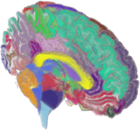
As I don’t think highly of the rendering results produced by the vtkVolumeRayCastMIPFunction class and vtkVolumeRayCastIsosurfaceFunction classes, I chose to demonstrate the usage of the vtkVolumeRayCastCompositeFunction class. Let’s take a look at the code:
funcRayCast = vtk.vtkVolumeRayCastCompositeFunction()
funcRayCast.SetCompositeMethodToClassifyFirst()

mapperVolume = vtk.vtkVolumeRayCastMapper()
mapperVolume.SetVolumeRayCastFunction(funcRayCast)
mapperVolume.SetInput(imdataBrainSeg)

actorVolume = vtk.vtkVolume()
actorVolume.SetMapper(mapperVolume)
actorVolume.SetProperty(propVolume)

renderer = createDummyRenderer()
renderer.AddActor(actorVolume)

vtk_show(renderer, 600, 600)
As you can see, we first create a new object called funcRayCast of type vtkVolumeRayCastCompositeFunction. Then we set the function to first classify the pixels it encounters before interpolating through the SetCompositeMethodToClassifyFirst method. This keeps the labels relative homogenized but if we decided to go the other way around with the SetCompositeMethodToInterpolateFirst method, the different labels would get mangled and we’d get a messy rendering (just change it and see).
Next, we need to create a volume mapper. As discussed we create a new vtkVolumeRayCastMapper object under the name of mapperVolume and feed it the newly created ray-casting function funcRayCast through the SetVolumeRayCastFunction method. Lastly, we feed it the actual image data we’re rendering which are stored in the imdataBrainSeg object.
Remember: The
vtkVolumeRayCastMapperclass only works withunsigned charandunsigned shortdata which is why we cast the image data upon loading it.
Subsequently, we create a vtkVolume object under actorVolume which is the equivalent of a vtkActor but meant for volumetric data. We set the mapper to mapperVolume and the properties to the vtkVolumeProperty object propVolume we created during the preparation.
Lastly, we just go through the pre-rendering motions. We create a new renderer through the createDummyRenderer helper-function we defined in the beginning and add actorVolume to it before calling vtk_show on it. The results can be seen in the next figure.
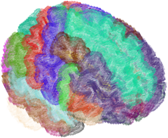
Well… that looks rather crummy doesn’t it? The dataset just has way too many tissues and the cerebral gyri just mix with one another, ’twas a hard customer. We could have improved the result by carefully configuring the opacity functions but that wasn’t the point of this post. At the very least let’s take a look through the volume so we can at least feel like we’ve rendered a volume.
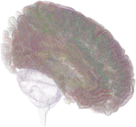
Clipping
The vtkVolumeRayCastMapper class, and really all volume mappers I’m aware of in VTK, support clipping! In order to use clipping we first need to create a plane with the appropriate location and orientation. Here’s how its done:
_origin = l2n(imdataBrainSeg.GetOrigin())
_spacing = l2n(imdataBrainSeg.GetSpacing())
_dims = l2n(imdataBrainSeg.GetDimensions())
_center = n2l(_origin+_spacing*(_dims/2.0))

planeClip = vtk.vtkPlane()
planeClip.SetOrigin(_center)
planeClip.SetNormal(0.0, 0.0, -1.0)
The above is as simple as anything so here comes the short version: We’re using the appropriate methods of the vtkImageData to retrieve the origin coordinates, spacing, and dimensions of our image data and use the l2n helper-function to quickly convert those lists to numpy.ndarray objects allowing us to perform some math with them. Then, we calculate the center coordinates of the image data and store it under _center.
All we then need to do is create a new vtkPlane, set its origin to the center of the image data, and its normal to the negative Z axis. Then we just repeat the volume-rendering code that we saw just before:
funcRayCast = vtk.vtkVolumeRayCastCompositeFunction()
funcRayCast.SetCompositeMethodToClassifyFirst()

mapperVolume = vtk.vtkVolumeRayCastMapper()
mapperVolume.SetVolumeRayCastFunction(funcRayCast)
mapperVolume.SetInput(imdataBrainSeg)
mapperVolume.AddClippingPlane(planeClip)

actorVolume = vtk.vtkVolume()
actorVolume.SetMapper(mapperVolume)
actorVolume.SetProperty(propVolume)

renderer = createDummyRenderer()
renderer.AddActor(actorVolume)

vtk_show(renderer, 800, 800)
Note that the one and only difference between the above snippet and the one before it is the following line that adds this newly created clipping plane to the volume mapper:
mapperVolume.AddClippingPlane(planeClip)
The result of the previous snippet can then be seen in the next figure.
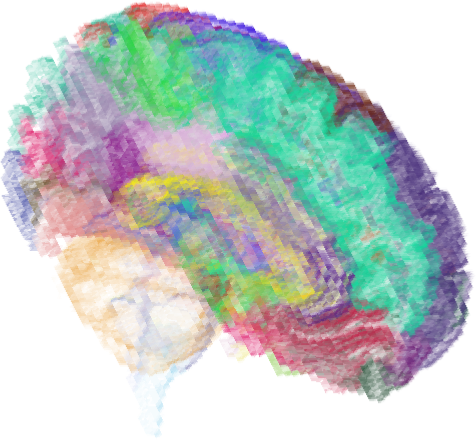
Now while still not particularly pretty, at least we can see a little more.
vtkVolumeTextureMapper2D
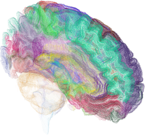
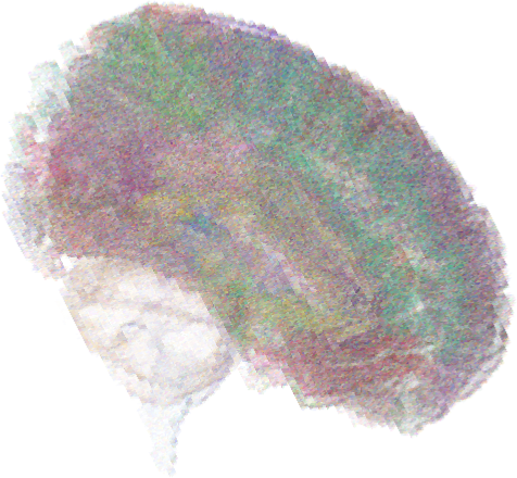
Now since I’d like at least one pretty picture for this post I’ll show you how to perform volume rendering with another of VTK’s volume mappers, particularly the vtkVolumeTextureMapper2D class.
This class uses texture-based volume rendering which happens entirely on the GPU side and generates much prettier, IMHO, renders in very little time. Let’s see the code:
mapperVolume = vtk.vtkVolumeTextureMapper2D()
mapperVolume.SetInput(imdataBrainSeg)
mapperVolume.AddClippingPlane(planeClip)

actorVolume = vtk.vtkVolume()
actorVolume.SetMapper(mapperVolume)
actorVolume.SetProperty(propVolume)

renderer = createDummyRenderer()
renderer.AddActor(actorVolume)

vtk_show(renderer, 800, 800)
As you can see, the only difference from the above code and the snippets we saw before is that mapperVolume is now of type vtkVolumeTextureMapper2D instead of vtkVolumeRayCastMapper. Also, you may notice we’re not defining any ray-casting functions as this isn’t how this class operates. Apart from those differences, the remainder of the code is identical to before. The results can be seen in the following figure.
Outro
Much like segmentation, volume rendering is a hit-n-miss process. Defining the transfer functions, choosing the right lighting/shading volume properties, choosing and configuring the appropriate volume mapper etc etc. All these things are pivotal to the result of the rendering and can make or break it.
You can, and should, experiment with the different settings till the cows come home (or until you’re satisfied with the result). Don’t forget to play with the different ray-casting functions that can be applied to the vtkVolumeRayCastMapper class. Also, before I conclude I’d like to draw your attention to a couple more volume-mapping classes you can play around with:
vtkGPUVolumeRayCastMapper: An GPU version ofvtkVolumeRayCastMapperclass which just didn’t want to work on my MacBook’s NVIDIA GeForce GT 750M but worked on my desktop’s GTX 750i (so don’t be surprised if it doesn’t work for you). Its much less customizable than its CPU counterpart and seemed to ignore the gradient opacity function but the result was still pretty so I included it below. In addition, this class is undergoing a revamping as stated in this recent update on the topic by Kitware so its good to keep it in mind.
vtkFixedPointVolumeRayCastMapper: A good replacement for thevtkVolumeRayCastMapperclass. UnlikevtkVolumeRayCastMapperit supports any data type, multi-component image data, and is implemented with multi-threading thus being much faster. It comes with a couple restrictions though, e.g., only supports the ‘interpolate-first’ ray-casting approach which doesn’t produce nice results with this dataset hence I didn’t present it but in case you were wondering you can see the result below. I should note that this messy result is pretty much what I got when used ‘interpolate-first’ with thevtkVolumeRayCastMapperclass.
vtkVolumeTextureMapper3D: As the name implies this volume mapper perform full–3D texture mapping with the volumetric dataset. You can see the non-pretty result below but keep the class in mind. If you want to read up on the texture-mapping and the difference between 2D and 3D texture mapping I suggest you check this article.
vtkSmartVolumeMapper: Special mention should go to this class, which is “is an adaptive volume mapper that will delegate to a specific volume mapper based on rendering parameters and available hardware”. This volume mapper ‘checks’ your input data and depending on their data type, number of components per pixel, available hardware, and whether the rendering will be interactive or still, chooses the ‘best’ volume mapper for the job. I should also note that this class will soon be the primary interface for volume rendering in VTK as stated in this recent update on the topic by Kitware and will continue to be updated with the entire volume-rendering arsenal VTK has to offer so keep an eye on it.
Note that the above renderings, created with the corresponding classes, can be found in today’s notebook for your reference and experimenting. I just didn’t think they were worth detailing as the code is only 1–2 lines different than the code discussed in this post.
Links & Resources
Material
Here’s the material used in this post:
- IPython Notebook with the entire process.
- Modified Brain Atlas Dataset used in this post.
Volume Rendering Resources
Here are a few resources on volume rendering:
- VTK User’s Guide: The official book on VTK by Kitware. The latest edition, 11th at the time of writing, has an entire chapter dedicated to volume rendering with VTK, while older editions have a lot of material on it as well.
- Introduction to Programming for Image Analysis with VTK: A great, free book on medical image processing with VTK. While it’s a little outdated, the vast majority of information presented in this book is still applicable to current versions of VTK and its definitely worth a read. Chapter 12 contains a large section on volume rendering as well.
- CS 6630 : Scientific Visualization: Project 4 – Volume Rendering: A nice report on volume rendering with VTK from the Utah School of Computing’s ‘Scientific Visualization’ course. It gives a very nice overview of the different aspects of volume rendering with VTK as well as a series of scripts to reproduce the presented renderings.
- Interactive Volume Rendering Using 3D Texture-Mapping Hardware: An article on texture-mapping volume rendering and the difference between 2D and 3D texture-mapping.
See also
Check out these past posts which were used and referenced today or are relevant to this post:
- Anaconda: The crème de la crème of Python distros
- IPython Notebook & VTK
- Surface Extraction: Creating a mesh from pixel-data using Python and VTK
- Ray Casting with Python and VTK: Intersecting lines/rays with surface meshes
- From Ray Casting to Ray Tracing with Python and VTK
- Image Segmentation with Python and SimpleITK
- Multi-Modal Image Segmentation with Python & SimpleITK
Don’t forget: all material I’m presenting in this blog can be found under the PyScience BitBucket repository.

Pingback: Python access to the Cancer Imaging Archive (TCIA) through a REST API | PyScience
Pingback: Volume Rendering | Audio Sketches
Today’s dataset is a dead link. So the color file cannot be found.
LikeLike
Oh rats. Bitbucket must’ve changed the way they expose repo files for HTTP download. You can get the file from the repo, clone or download the whole repo as zip, itself and I’ll fix the links ASAP
LikeLike
Thanks, this worked. Short follow up question. I want to apply volume rendering to a different CT dataset. I followed some of your other blogs and went from dicom over simpleITK to numpy to vdk array and finally to vdk data object. I normalized the numpy array to have values between 0 and 149 and made sure that everything is cast to unsigned short.
If I run the script with your brain data I get a neat render of the brain. If I run it on my vdk object I simply get a white box. Resetting the background hex still does not change the output image.
A histogram of the pixel values in my data set shows almost uniform distribution between 0 and 60 and afterwards next to nothing.
How can I check that my vdk object is valid and complete? How would you go about adapting the transfer functions?
Thank you for your efforts, this is highly appreciated.
LikeLike
Well without having access to your dataset itself, which I understand if you can’t share, I can only provide educated guesses. Is your dataset segmented? Are you trying to display a labelfield or an actual DICOM image? As you can see in the presented code I’m setting the colour-transfer-function to give a unique colour to each label index. If your dataset has values of 0 to 60 I’d say you should’ve still seen something coming up.
I’d suggest you first try to volume-render your dataset through Paraview (http://www.paraview.org/) which uses the exact-same VTK backend as the presented code. If it works there it might just mean that there was an issue in your conversion of the dataset from SimpleITK to NumPy to VTK. Did you do any matplotlib plots on the intermediate NumPy array to verify that your data is still ok?
LikeLike
Thanks, I got it working now. I would finally like to generate a mesh for a CFD simulation from the dataset. Now that I can perform segmentation on the numpy.array I am not sure how to proceed. Do you have experience with either converting the volume or the surface rendering into a mesh for FE or CFD simulations? Any pointer would be great, as I am mainly guessing around here…
Thank you!
LikeLike
I have a post on extracting a mesh from a dataset under https://pyscience.wordpress.com/2014/09/11/surface-extraction-creating-a-mesh-from-pixel-data-using-python-and-vtk/. That will give you an ok mesh but its rarely good enough for a CFD simulation. What’s more that mesh is going to be a triangular surface mesh rather than a tetrahedral mesh. Unfortunately, to my knowledge VTK doesn’t come with a proper tetra-mesher. You could generate the surface mesh with the above post, use something like Meshlab (http://meshlab.sourceforge.net/) or Geomagic Studio (http://www.geomagic.com/en/) to clean it up (make the triangles all nice and uniform, remove self-intersecting triangles, correct normals, etc) and then you could employ meshers like CGAL (http://doc.cgal.org/latest/Mesh_3/), TetGen (http://wias-berlin.de/software/tetgen/) or NetGen (http://sourceforge.net/projects/netgen-mesher/files/netgen-mesher/5.0/) to create a tetra-mesh. The latter two have been wrapped in a Python package called MeshPy (https://pypi.python.org/pypi/MeshPy) making them a little more approachable than CGAL. Good luck though cause you’re getting yourself in the scary world of meshing 😀
LikeLike
Can’t say what happened before but the links appear to work now 🙂
LikeLike
Hi, perhaps you has a example in python and vtk to make a 3d volume with dicom or png files? Thanks
LikeLike
Not sure what you mean there. Just follow the process shown in the DICOM post to load the images into a single vtkImageData object and then use that for volume rendering. Did you mean something different
LikeLike
I’m beginner in vtk, for example, i have a directory with my png files, my idea is read this directory, catch all files and after generate the volume. I do not have a file .mha
LikeLike
For a series of image files you can either use VTK’s vtkPNGReader (http://www.vtk.org/Wiki/VTK/Examples/Cxx/IO/PNGReader) in a loop which may be confusing or better yet SimpleITK’s ImageSeriesReader (http://www.itk.org/SimpleITKDoxygen/html/classitk_1_1simple_1_1ImageSeriesReader.html). Then once your images are loaded in a SimpleITK Image object you can convert that to a NumPy array and then a vtkImageData object in order to visualise it 🙂
LikeLike
Great, thanck you very much, I will try now
LikeLike
First – great notebook! Super helpful!
Second – there’s a small gliche, I’m not sure if it’s a version issue but the mapperVolume instance created with vtk.vtkImageCast() spits out an error when trying to call mapperVolume.SetInput
I looked up the help for that instance and it seem like changing it to the following resolved the issue:
mapperVolume.SetInputData
Thanks and keep on posting!
Matan
LikeLike
Hi Matan and thanks for the kind words. You know what you’re describing sounds awfully familiar. All my code was written on VTK5 while in the past 1.5yrs since I’ve bothered to post Anaconda graciously compiled and provided VTK6 which changes a fair few things in the interface. If you wanna run my notebooks you might want to create a separate Anaconda environment with `vtk==5.10.1` which is what I was using.
LikeLike
Rolling back versions seems to solve it.
But shortly following your suggestion I found mayavi which pretty much covers all my needs.
Thanks again!
LikeLike
Just amazing…!! Thqs a lot
LikeLike
Thank you 🙂
LikeLike
I had some issues getting this running in 3.6, Seems like they have changed the render pipeline. Here are the changes I made:
When reading in the data you need to return an output port, not an output:
imdataBrainSeg = castFilter.GetOutput()
>>REPLACE
imdataBrainSeg = castFilter.GetOutputPort()
Store the output object in a new reference:
>>ADD
idbs = castFilter.GetOutput()
The rendering pipeline has changed significantly. Check the notebook, Find the block which starts with:
funcRayCast = vtk.vtkVolumeRayCastCompositeFunction()
…
vtk_show()
>>REPLACE
volumeMapper = vtk.vtkFixedPointVolumeRayCastMapper()
volumeMapper.SetInputConnection(imdataBrainSeg)
volume = vtk.vtkVolume()
volume.SetMapper(volumeMapper)
volume.SetProperty(propVolume)
renderer = vtk.vtkRenderer()
renderWin = vtk.vtkRenderWindow()
renderWin.AddRenderer(renderer)
renderInteractor = vtk.vtkRenderWindowInteractor()
renderInteractor.SetRenderWindow(renderWin)
colors = vtk.vtkNamedColors()
# We add the volume to the renderer …
renderer.AddVolume(volume)
renderer.SetBackground(colors.GetColor3d(“MistyRose”))
# … and set window size.
renderWin.SetSize(400, 400)
# A simple function to be called when the user decides to quit the application.
def exitCheck(obj, event):
if obj.GetEventPending() != 0:
obj.SetAbortRender(1)
# Tell the application to use the function as an exit check.
renderWin.AddObserver(“AbortCheckEvent”, exitCheck)
#Init
renderInteractor.Initialize()
# Because nothing will be rendered without any input, we order the first render manually
# before control is handed over to the main-loop.
renderWin.Render()
renderInteractor.Start()
This should set up the new render method, You will need to add references to your volume, colors etc. In the following block where you set _origin etc, rename imdataBrainSeg (which is now an OutputPort ref) to ibds which references the actual vtkImgData
LikeLike
Thanks a lot for the upgrade notes Nadir! Hopefully it’ll make it easier for people to port the code over to Py3.
As you discovered the APIs have changed quite a bit in the latest versions making a lot of my posted code unusable in Python 3. Part of the reason I haven’t posted in forever since I’d need to go back and redo all the posts bringing the whole blog into Python 3 😂.
LikeLike
No worries, This probably isnt the best way to do it, but it seems to be working for now. Looking online there seems to be little information regarding the new VTK API, I am not sure if there is a newer library which is seeing wider use, But its certainly usable still
LikeLike
Honestly I’ve been asking myself that question for years “Given what VTK can do and its minimal documentation, is there an alternative out there that’s more used or better documented?”. During my PhD years VTK was “the one” but knowledge seemed to be accrued through suffering and experimentation and never shared so the question remains unanswered 😂. At the end of the day it seems to come down to trial-n-error.
LikeLike
Yep, It seems like theres no real open source toolkit other than VTK, possibly a bunch of proprietary visualization tools, but those arent very useful if you need to create automated processes which run quickly. If you hear of any, feel free to let me know!
LikeLiked by 1 person
I also have a question, If anyone knows how to generate volumetric data output of the vtkImgData/CT slices.
From what I can see, The Volume renderer is sent an array of pixel values with spacing which is all calculated from the reader process. When we access it, there is an array of pixes and metadata, But there are no XYZ coords for each point on a slice.
When that data is sent into the volume renderer, it probably does some transformation to create the XYZ representation, However it isnt a publicity accessible function, just part of the rendering process.
I can write out a .vtk structured points file doing the following
pw = vtk.vtkStructuredPointsWriter()
pw.SetInputConnection(imdataBrainSeg.GetOutputPort())
pw.SetFileName(“volume.vtk”)
pw.Write()
This writes the vtkImgData out as a set of structured points, specifying each points value if you were to step through cloud using the spacing and dimensions parameters as defined in the header of the .vtk file. This doesnt write XYZ data per-point, and there are a lot of “empty” points which need to be stepped through, not ideal. I need a sparse point cloud which only has xyz data (possibly an attribute) per-point which has been thresholded. And it needs to be written out as a common point cloud file type, such as XYZ, TXT, PTS, LAS.
Is there some solution to this, such as a function which can convert the vtkImgData array into an array of XYZ values? I have tried searching the API, As well as PCL (Point Cloud Library) but it seems like there is no conversion code available in Python.
LikeLike
Hi Nadir! From what I’m gathering you’re trying to convert a vtkImageData object to a point cloud but as I showed in the original post the volume rendered is happy to work with an MHD file which doesn’t seem to have coordinates per pixel. Can you explain why you’re trying to pull out points?
LikeLike
Hey, Thanks for the reply. I am looking to author assets (Volume Textures/Point Clouds) for the Unreal Engine, So the data can be visualized and interacted with.
We need to create an automated converter for DICOM data and possibly other formats. I am assuming MHD contains similar data (3d arrays of 2d image scans) as VTK can read it and generate a vtkImageData object. I am trying to find how I can convert that data into a point cloud which can then be used to drive a raymarcher or voxel render.
LikeLike
So even if you convert image-data to point-clouds will those be compatible with whatever assets the Unreal Engine supports or would you be coding a custom renderer? Is there a particular format you’re aiming at? If you’re just looking at rendering actual voxels then a standard .vti format should work right (https://kitware.github.io/vtk-js/examples/VolumeViewer.html)?
LikeLike
For now the general approach is to use a volumetric ray marcher, indexing through a flipbook (image slices) of the data. That is done by writing a custom shader, However there are recent developments using point cloud technology too, So the main focus is finding a pipeline which can convert volume slices into generic point cloud data. The unreal plugin supports XYZ/TXT point cloud files, which are ASCII encoded tables which contain a points XYZ + Other attributes per line (similar to CSV). Regarding voxels, well the point data should be driving a voxel generator in the engine, I am not sure if voxel files themselves would be needed because they may contain too much data
I found the point cloud library (PCL) which can author point cloud data (PCD) files as seen here:
http://pointclouds.org/documentation/tutorials/pcd_file_format.php
It seems like it there is a VTK to PCD function, However, UE4’s point cloud plugin only imports XYZ, TXT, PTS, LAS currently. So it looks like I need to convert VTK to PCD and then to LAS.
VTK: Publish .vtk ordered points
PCL: .vtk to .pcd file (think this creates xyz locs using vtk metadata such as grid size and point count, and the index of the entry)
PDAL: .pcd to .las (PCL only has one-way converstion (LAS to PCD) so need to use another lib)
Besides writing my own converter, this seems like the only way currently. PCL and PDAL are written in platform-dependent C++ so creating the automated pipeline would be a nightmare. I am looking for some kind of library which can generate point clouds from image slices, and publish them in a variety of file formats, but seemingly there isn’t anything available,
LikeLike
Honestly the XYZ/CSV format seems simple enough, will account for sparseness, and its simplicity seems to be why there’s no “official” converters within VTK for it. You’re probably better off writing your own converter for it rather than trying to glue together 2-3 different libraries. Now I haven’t tried it but vtkDelimitedTextWriter (https://discourse.vtk.org/t/save-polydata-to-csv-using-vtkdelimitedtextwriter/986) might be able to do what you need without you having to convert to a Python object and then iterate so it could be fast enough if the output works with UE4.
LikeLike
hello sir somada141 I am unable to run the given code what changes I need to do as this is 2014 post
this article is very well written, I loved the content.
LikeLike
Hey Maharaj! Reckon the code needs to be ran in a Python 2 environment with VTK v5. If you follow the instructions under the Anaconda post you should be able to pull it off
LikeLike
sir vtk 5 is not available any where can you help me a bit more
The code after volumetric rendering is not working
LikeLike