In this post I will demonstrate SimpleITK, an abstraction layer over the ITK library, to segment/label the white and gray matter from an MRI dataset. I will start with an intro on what SimpleITK is, what it can do, and how to install it. The tutorial will include loading a DICOM file-series, image smoothing/denoising, region-growing image filters, binary hole filling, as well as visualization tricks.
Introduction
I think that by this point you may’ve had enough of VTK and its obscure, bordering on the occult, inner-workings. I admit that the topics I covered so far were not that much about visualization but mostly about ‘secondary’ functionality of VTK. However, information and examples on the former can be found with relative ease and I’ve posted a few such links in this early post about IPython & VTK.
Today I’ll be branching off and talking about its cousin, the Insight Segmentation and Registration Toolkit (ITK), a library created by the same fine folk as VTK, i.e., Kitware, but which focuses on image processing.
Background
Insight Toolkit (ITK)
ITK was originally built to support the ‘Visible Human’ project, which we used in this past post about surface extraction. It includes a whole bunch of goodies including routines for the segmentation, registration, and interpolation of multi-dimensional image data.
Just like VTK, ITK exhibits the same mind-boggling design paradigms and near-inexistent documentation (apart from this one book and some little tidbits like the Doxygen docs, a couple presentations, and webinars).
Nonetheless, just like VTK, ITK offers some amazing functionality one just can’t overlook in good conscience. Its no coincidence ITK is being heavily employed in image processing software like ParaView, MeVisLab and 3DSlicer. It just works!
SimpleITK
Today, however, we won’t be dealing with ITK, but SimpleITK instead! SimpleITK is, as the name implies, a simplified layer/wrapper build on top of ITK, exposing the vast majority of ITK functionality through bindings in a variety of languages, greatly simplifying its usage.
While the usage of ITK would require incessant usage of templates and result in code like this:
// Setup image types.
typedef float InputPixelType;
typedef float OutputPixelType;
typedef itk::Image<InputPixelType, 2> InputImageType;
typedef itk::Image<OutputPixelType, 2> OutputImageType;
// Filter type
typedef itk::DiscreteGaussianImageFilter<InputImageType, OutputImageType> FilterType;

// Create a filter
FilterType::Pointer filter = FilterType::New();

// Create the pipeline
filter−>SetInput(reader−>GetOutput());
filter−>SetVariance(1.0);
filter−>SetMaximumKernelWidth(5);
filter−>Update();
OutputImageType::Pointer blurred = filter−>GetOutput();
SimpleITK hides all that characteristically un-pythonic-code and yields something like this:
import SimpleITK
imgInput = SimpleITK.ReadImage(filename)
imgOutput = SimpleITK.DiscreteGaussianFilter(imgInput, 1.0, 5)
However, the power of SimpleITK, doesn’t end in allowing for succinct ITK calls. Some very notable features are:
– Super-simple IO of multi-dimensional image data supporting most image file formats (including DICOM through the infamous Grassroots DICOM library (GDCM), more on that later).
– A fantastic SimpleITK.Image class which handles all image data and which includes overloads for all basic arithmetic (+ - * / // **) and binary (& | ^ ~) operators. These operators just wrap the corresponding ITK filter and operate on a pixel-by-pixel basis thus allowing you to work directly on the image data without long function calls and filter configuration.
– Slicing capability akin to that seen in numpy.ndarray objects allowing you to extract parts of the image, crop it, tile it, flip it, etc etc. While slicing in SimpleITK is not as powerful as NumPy, its still pretty darn impressive (not to mention invaluable)!
– Built-in support for two-way conversion between SimpleITK.Image object and numpy.ndarray (there’s a catch though, more on that later as well).
– No pipeline! Those who read my previous posts on VTK, will be aware of that pipeline monstrosity VTK is built upon. Well, SimpleITK does away with that and all operations are immediate (a much more pythonic paradigm).
You’ll find a fair number of links to SimpleITK material at the end of this post.
Installation
For better or for worse, SimpleITK isn’t written in pure Python but rather C++ which translates to you needing a compiled version of the library. Unfortunately, SimpleITK doesn’t come pre-compiled with any of the major alternative Python distros I know so if you’re using Anaconda Python, Enthought Python, Enthought Canopy, or even the OSX MacPorts or Homebrew Python, installing it is a lil’ hairier than normal.
Vanilla Python
If you’re using a vanilla Python interpreter, i.e., a Python distro downloaded straight from python.org, or the ‘system Python’ that comes pre-installed with most Linux and OSX distros, then you’re in luck! You can simply install the SimpleITK package hosted on PyPI through pip as such:
pip install SimpleITK
Alternatively, you can install it by using easy_install and one of the Python eggs (.egg), or pip and one of the Python wheels (.whl) provided at the SimpleITK download page as such:
easy_install <egg filename>
or
pip install --use-wheel <whl filename>
In case you’ve missed the news, Python wheels (
.whl) are meant to replace Python eggs (.egg) in the distribution of binary Python packages. Installing them is performed throughpip install --use-wheel <whl filename>but you must have first installed thewheelpackage throughpip install wheel.
Anaconda Python
Unfortunately, here’s where the trouble starts. Alternative Python distros like the Anaconda Python, Enthought Python, Enthought Canopy, or even the OSX MacPorts and Homebrew Python, have their own version of the Python interpreters and dynamic libraries.
However, the aforementioned SimpleITK wheels and eggs are all compiled and linked against vanilla Python interpreters, and should you make the very common mistake of installing one of those in a non-vanilla environment, then upon importing that package you’ll most likely get the following infamous error:
Fatal Python error: PyThreadState_Get: no current thread
This issue, however, isn’t exclusive to SimpleITK. Any package containing Python-bound C/C++ code compiled against a vanilla Python will most likely result in an error if used in a different interpreter. Solution? To my knowledge you have one of three options:
- Compile the code yourself against the Python interpreter and dynamic library you’re using.That of course includes checking out the code, ensuring you already have (or even worse compile from source) whatever dependencies that package has, and build the whole thing yourself. If you’re lucky, the source-code will come with CMake’s Superbuild and the process will just take a couple hours of tinkering. If not, you can spend days trying to get the thing to compile without errors, repeating the same bloody procedure over and over and harassing people online for answers.In the case of SimpleITK there are instructions on how to do so under the ‘Building using SuperBuild’ on their Getting Started page. However, a process like this typically assumes a working knowledge of Git, CMake, and the structure of your non-vanilla Python distribution.
- Wait patiently till the devs of your non-vanilla Python distro build the package for you and give you a convenient way of installing it.Companies like Continuum Analytics (creators of Anaconda Python) and Enthought often do the work for you. That’s exactly why you have packages like VTK all built and ready with those distros. However, in the case of less-popular packages, SimpleITK being one, you might be waiting for some time till enough people request it and the devs take time to do so.
- Depend on the kindness of strangers. Often enough, other users of non-vanilla Python distros will do the work described in (1) and, should they feel like it, distribute the built package for other users of the same distro.
This last one is exactly the case today. I compiled the latest SimpleITK release (v0.8.0) against an x64 Anaconda Python with Python 2.7 under Mac OSX 10.9.5, Windows 8.1, and Linux Mint 17 and I’m gonna give you the .egg files you need to install the package. You can get the .egg files here (hosted on the blog’s BitBucket repo):
- SimpleITK .egg for Anaconda Python 2.7 on Windows x64
- SimpleITK .egg for Anaconda Python 2.7 on Linux x64
- SimpleITK .egg for Anaconda Python 2.7 on Mac OSX x64
Here I should note that the above, i.e., people distributing their own builds to save other people the trouble of doing so themselves, is not that uncommon. Its actually the primary reason behind the creation of Binstar, a package distribution system by the creators of Anaconda Python, principally targeting that distro, meant to allow users to redistribute binary builds of packages and permitting them to be installed through
conda. There you will find many custom-built packages such as OpenCV, PETSc, etc but I’ll get back to Binstar at a later post. However, I didn’t find the time to package SimpleITK on Binstar hence .egg files it is for now :).
If you’re using Anaconda Python the you simply need to download the appropriate .egg and install it through easy_install <egg filename>. Uninstalling it is as easy as pip uninstall simpleitk.
If you’re using an Anaconda environment, e.g. named
py27environment as instructed in this past post, then you need to activate that environment prior to installing the package throughactivate py27(Windows) orsource activate py27(Linux/OSX). Also, make sure that environment containspipandsetuptoolsbefore installing the.egg. Otherwise,pipwill be called through therootAnaconda environment and be installed in that environment instead.
Summary
The purpose of today’s post was to introduce you to SimpleITK, show you how to install it, and give you a taste of its image-processing prowess.
Personally, when I started this blog I intended to only address challenging yet IMHO interesting topics that I once found hard to tackle, and powerful tools that either suffered from poor/insufficient documentation or were not as prominent in the community as they deserve to be.
SimpleITK falls under the latter category. I find the package to be as easy and Pythonic as a Python-bound C++ package can be. In addition, there’s a whole treasure-trove of functionality one just can’t find elsewhere. However, I find the existing documentation lacking and perhaps its due to the fact that people don’t know of its existence.
Hence, today I’ll do a little demonstration of some of SimpleITK’s functionality, and use it to semi-automatically segment the brain-matter (white and gray) off an MRI dataset of my own head (of which I first spoke in this past post about DICOM in Python). You can download that dataset here and you should extract its contents alongside today’s notebook.
The process will include loading the series of DICOM files into a single SimpleITK.Image object, smoothing that image to reduce noise, segmenting the tissues using region-growing techniques, filling holes in the resulting tissue-labels, while I’ll also show you a few visualization tricks that come with SimpleITK.
However, keep in mind that the presented functionality is the mere tip of a massive iceberg and that SimpleITK offers a lot more. To prove that point, I repeated the process in today’s notebook in an ‘alternative notebook’ where I used different techniques to achieve similar results (feel free to take a look cause I won’t be going over this ‘alternative notebook’ today). In addition, and as I mentioned in the intro, SimpleITK comes with a lot of classes tailored to image registration, interpolation, etc etc. I may demonstrate things like that in later posts.
Image Segmentation
Imports
As always we’ll start with a few imports. Nothing special but if this goes through that means that you’re installation of SimpleITK probably worked :).
import os
import numpy
import SimpleITK
import matplotlib.pyplot as plt
%pylab inline
Helper-Functions
There’s only going to be a single ‘helper-function’ today:
sitk_show(img, title=None, margin=0.05, dpi=40): This function usesmatplotlib.pyplotto quickly visualize a 2DSimpleITK.Imageobject under theimgparameter. The code is pretty much entirelymatplotlibbut there’s one point you should pay attention to so here’s the code:
def sitk_show(img, title=None, margin=0.05, dpi=40 ):
    nda = SimpleITK.GetArrayFromImage(img)
    spacing = img.GetSpacing()
    figsize = (1 + margin) * nda.shape[0] / dpi, (1 + margin) * nda.shape[1] / dpi
    extent = (0, nda.shape[1]*spacing[1], nda.shape[0]*spacing[0], 0)
    fig = plt.figure(figsize=figsize, dpi=dpi)
    ax = fig.add_axes([margin, margin, 1 - 2*margin, 1 - 2*margin])

    plt.set_cmap("gray")
    ax.imshow(nda,extent=extent,interpolation=None)

    if title:
        plt.title(title)

    plt.show()
As you can see in the first line of the function we convert the SimpleITK.Image object to a numpy.ndarray through the GetArrayFromImage function which resides directly under the SimpleITK module. The opposite can be done through the GetImageFromArray function which just takes a numpy.ndarray and returns a SimpleITK.Image object.
However!, there’s a serious catch to this conversion! Be careful! If you were to have a SimpleITK.Image object with a size/shape of 200x100x50, then upon conversion to a numpy.ndarray that object would exhibit a shape of 50x100x200, i.e., the axes would be backwards.
The reason behind this is briefly outlined in this SimpleITK notebook by the SimpleITK author. It turns out that the SimpleITK.Image class doesn’t exactly have a bracket ([ and ]) operator but instead uses the GetPixel method which takes in a pixel index in a (x, y, z) order, i.e., the internal array is stored in an ‘x-fastest’ fashion. However, numpy internally stores its arrays in a ‘z-fastest’ fashion and takes an index in a (z, y, x) order. As a result you get the axes backwards!
Now, what does that mean for you? Well for one it means you need to be careful with your indices depending on whether you’re addressing the SimpleITK.Image or a numpy.ndarray derivative. It also means that the result of the sitk_show helper-function, which uses the GetArrayFromImage method we’re discussing, shows you the numpy view of the array and needs to be taken with a grain of salt. Lastly, when you feed point indices to SimpleITK for different algorithms, as we’ll see later, these indices need to be in the SimpleITK order and not the NumPy order.
I should state here that one can easily use
numpy.transposeto bring the axes in the derivativenumpy.ndarrayin their ‘proper’ order. However, the array within SimpleITK is what it is and unless you just want to use SimpleITK to load data and then play around with NumPy there’s little point to it.
Options
Once again, we’ll define a few options to keep the rest of the notebook ‘clean’ and allow you to make direct changes without perusing/amending the entire notebook.
# Directory where the DICOM files are being stored (in this
# case the 'MyHead' folder).
pathDicom = "./MyHead/"

# Z slice of the DICOM files to process. In the interest of
# simplicity, segmentation will be limited to a single 2D
# image but all processes are entirely applicable to the 3D image
idxSlice = 50

# int labels to assign to the segmented white and gray matter.
# These need to be different integers but their values themselves
# don't matter
labelWhiteMatter = 1
labelGrayMatter = 2
First of all we define the path where the .dcm files are under, i.e., pathDicom. Once more, you can get the MRI dataset of my head under here whose contents you should extract next to today’s notebook.
I want to emphasize the 2nd option. As I explain in the comments, I’m going to be limiting the segmentation to a single 2D slice of the DICOM dataset. The reason for this is not because the process would become too computationally expensive (clearly slower but not by much) but rather for the sake of clarity.
When it comes to image segmentation, and especially when using algorithms based on region-growing and pixel-connectivity, application to the full 3D image might yield non-intuitive results. For examples, regions might seem entirely disconnected when viewed on one cross-section but end up being connected further down the slices through some small structure. Therefore, and since I’ll only be using 2D visualization, I wanted to keep things clear.
I should stress that the code I’ll be presenting is entirely applicable to the full 3D image but the parameters used in the function calls, e.g. seed-point indices, won’t be. Image segmentation is mostly about trial-n-error so try away.
Lastly, note labelWhiteMatter and labelGrayMatter. These are simply two integer values, which will act as label indices in the segmentation as we want the different tissues to be characterized by a different index. Its as simple as that.
Loading the DICOM files
Now let’s move onto reading the DICOM files. Remember you have to extract the contents of the MRI dataset, i.e., my head, alongside today’s notebook.
reader = SimpleITK.ImageSeriesReader()
filenamesDICOM = reader.GetGDCMSeriesFileNames(pathDicom)
reader.SetFileNames(filenamesDICOM)
imgOriginal = reader.Execute()
Reading the entirety of the DICOM file series goes as follows: We start by creating a new ImageSeriesReader object under the name reader. We then use the GetGDCMSeriesFileNames static method of the ImageSeriesReader to retrieve a list of all .dcm filenames which we store under filenamesDICOM and which we then pass back to the reader through the SetFileNames method. Finally, by calling Execute we retrieve the entire 3D image under imgOriginal.
If you get a dead kernel here then please do check the console output. It might well be that you forgot to extract the DICOM files out of their .zip or that you’ve placed them under a different directory to the one under
pathDicom.
A very important point I want to stress here is that SimpleITK uses the Grassroots DICOM library (GDCM) to load DICOM files. As a result, those pesky JPEG compressed DICOM files, e.g., the ones found in the Osirix Datasets page, which we couldn’t load with either PyDICOM or VTK in the past post about Python and DICOM, are no longer a deterrence. GDCM is actually the most comprehensive DICOM library I know of so you should be able to handle pretty much any DICOM file :).
Then, as I mentioned in the Options section, we limit ourselves to a single 2D slice of the 3D volume. We do so by using the basic slicing offered by the SimpleITK.Image class:
imgOriginal = imgOriginal[:,:,idxSlice]
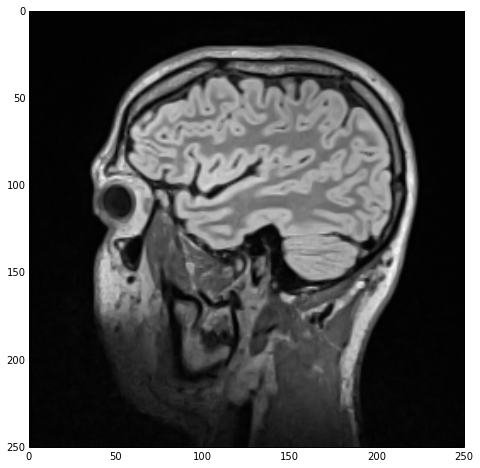
Finally, we use the sitk_show helper-function to visualize that 2D image which we will be segmenting:
sitk_show(imgOriginal)
which yields the next figure.
Note that, ironically, the white-matter (inner structure) appears as gray in the MR image while the gray-matter (outer structure) appears as white. Don’t let that throw you off :).

Smoothing/Denoising
As you can see from the above figure, the original image data exhibits quite a bit of ‘noise’ which is very typical of MRI datasets. However, since we’ll be applying region-growing and thresholding segmentation algorithms we need a smoother, more homogeneous pixel distribution. To that end, before we start the segmentation, we smoothen the image with the CurvatureFlowImageFilter. Here’s how we do that:
imgSmooth = SimpleITK.CurvatureFlow(image1=imgOriginal,
                                    timeStep=0.125,
                                    numberOfIterations=5)

# blurFilter = SimpleITK.CurvatureFlowImageFilter()
# blurFilter.SetNumberOfIterations(5)
# blurFilter.SetTimeStep(0.125)
# imgSmooth = blurFilter.Execute(imgOriginal)

sitk_show(imgSmooth)
The CurvatureFlowImageFilter class “implements a curvature driven image denoising algorithm”. The math behind this filter are based on a finite-differences algorithm and are quite convoluted. Should you feel like it, you can read more about the algorithm in the class’ docs.
A point I’d like to make here is that all of the image filters in SimpleITK can be called in one of two ways. The first way is to directly call a function, CurvatureFlow in this case, which nicely wraps all required filter parameters as function arguments (while also exposing optional arguments). This is the way we’re calling it above.
However, as you can see in the commented code, an alternative would be to create a filter object, CurvatureFlowImageFilter in this case, and set the required parameters one-by-one through the corresponding methods before calling the Execute method.
The above holds for all image filters included in SimpleITK. The filter class itself typically has an ImageFilter suffix while the corresponding wrapper function maintains the same name minus that suffix. Both approaches, however, wrap the same filters and which one to use is a matter of preference.
Henceforth I will be using the direct function calls in the code but I’ll be referencing the filter class as there’s no docs for the former.
Regardless of the calling-paradigm, we end up with a imgSmooth image which contains the results of the smoothing. Using sitk_show we get the following figure:
I should mention that image-smoothing is a very typical first step in the medical image data segmentation process, ‘required’ by the majority of segmentation algorithms.
Segmentation with the ConnectedThreshold filter
Initial segmentation of the white-matter
For the purposes of this post we’ll be segmenting the white and gray matter through the ConnectedThresholdImageFilter class, or rather the ConnectedThreshold function which wraps the former.
What this filter does is simply “label pixels that are connected to a seed and lie within a range of values”. Essentially, this filter operates on the input image starting from a series of given ‘seed points’. It then starts ‘growing’ a region around those points and keeps adding the neighboring points as long as their values fall within given thresholds. Let’s see how it’s done:
lstSeeds = [(150,75)]

imgWhiteMatter = SimpleITK.ConnectedThreshold(image1=imgSmooth,
                                              seedList=lstSeeds,
                                              lower=130,
                                              upper=190,
                                              replaceValue=labelWhiteMatter)
So, we start by create a list of tuple objects with the 2D indices of the seed points. As I mentioned in the Helper-Functions section, these indices need to abide by the order expected by SimpleITK i.e., (x, y, z). Through the previous figure we spot a good seed-point in the white-matter (inner structure of the brain) at an x index of 150 and a y index of 75. Also, upon inspection of the slice, an inspection I performed while viewing the data in Osirix, I could see that the white-matter pixels exhibited values, roughly, between lower=130 and upper=190 which we’ll be setting as the threshold limits. Lastly, we configure the filter to set a value of labelWhiteMatter to all pixels belonging to the white-matter tissue (while the rest of the image will be set to a value of 0). As a result of all this we get the imgWhiteMatter image.
Note that we operate on
imgSmoothand notimgOriginal. That was the whole point of de-noisingimgOriginalanyway right?
Next, the reasonable thing to do would be to inspect the result of the segmentation. We could simply use sitk_show, passing imgWhiteMatter, but all we would see would be a white-color label in a black backdrop which doesn’t exactly give us much insight. Therefore, we’ll instead view this newly acquired label overlaid with imgSmooth, i.e., the input-image we used for the segmentation, using the SimpleITK.LabelOverlayImageFilter class:
# Rescale 'imgSmooth' and cast it to an integer type to match that of 'imgWhiteMatter'
imgSmoothInt = SimpleITK.Cast(SimpleITK.RescaleIntensity(imgSmooth), imgWhiteMatter.GetPixelID())

# Use 'LabelOverlay' to overlay 'imgSmooth' and 'imgWhiteMatter'
sitk_show(SimpleITK.LabelOverlay(imgSmoothInt, imgWhiteMatter))
Here I want to stress the following point: the result of the de-noising, i.e., imgSmooth, comprises pixels with float values while the result of the segmentation is of int type. Mixing the two won’t work, or will at least have unforeseen results. Therefore, we need to first ‘rescale’ imgSmooth to the same integer range and then cast it so that the types of the two images, i.e., imgSmooth and imgWhiteMatter, match.
We do that by first using the RescaleIntensityImageFilter with its range to the default values of 0 and 255. Subsequently, we ‘cast’ the image to the same type as imgWhiteMatter by using the CastImageFilter and the GetPixelID method of the SimpleITK.Image class. As a result we get an integer version of imgSmooth dubbed imgSmoothInt.
We’ll be using
imgSmoothIntfor all subsequent label overlays but won’t repeat the rescaling/recasting. Keep the name in mind.
Finally, we overlay imgSmoothInt and imgWhiteMatter through the SimpleITK.LabelOverlayImageFilter class which creates a nice basic-color RGB depiction of the otherwise monochrome 2nd image. Using the sitk_show helper function we get the next figure.
Hole-filling
As you can see from the above figure, our initial segmentation is subpar at best. Not only did we ‘eat into’ the gray matter, with which we’ll deal later, but in addition there are numerous ‘holes’ in the white-matter label. Let’s start by rectifying this.
Hole-filling is a very standard procedure in image segmentation, especially when employing region-growing algorithms. The reason? Well often enough regions of the tissue exhibit pixel values outside the defined thresholds either due to excessive noise in the image or the nature of the tissue itself in the given region. Thankfully, SimpleITK provides us with an arsenal of filters to ameliorate such issues.
One such filter is the VotingBinaryHoleFillingImageFilter which in a nutshell “Fills in holes and cavities by applying a voting operation on each pixel”. I suggest you check the filter docs for details on the actual implementation but in layman’s terms what this filter does is check every ‘off’ pixel, i.e., a pixel with a backgroundValue, and sets it to a foregroundValue if the majority of the pixels around it also have a foregroundValue. Here’s how that’s done:
imgWhiteMatterNoHoles = SimpleITK.VotingBinaryHoleFilling(image1=imgWhiteMatter,
radius=[2]*3,
majorityThreshold=1,
backgroundValue=0,
foregroundValue=labelWhiteMatter)
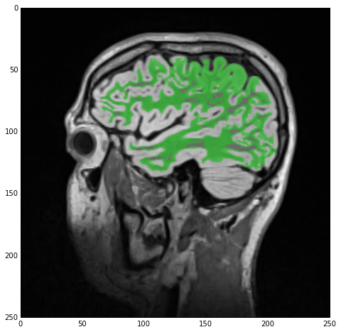
sitk_show(SimpleITK.LabelOverlay(imgSmoothInt, imgWhiteMatterNoHoles))
As you can see we once more skip the whole ‘initialize filter-configure filter-execute filter’ process and run the wrapper straight away. If my crummy explanation above wasn’t sufficient then off to the VotingBinaryHoleFillingImageFilter docs. Let me just say that the radius defines the pixel area/volume around a hole that is examined and the majorityThreshold is the number of pixels over 50% that need to be ‘on’ for that hole pixel to be turned ‘on’.
The result of the hole-filling operation is stored under imgWhiteMatterNoHoles and we once more overlay this new label with imgSmoothInt getting the next figure. As you can see the operation wasn’t wildly successful but many of the smaller holes were indeed filled. All this means is that we should’ve imposed looser criteria, e.g., a larger radius.

Segmentation of the gray-matter
Next we’ll repeat the process we just saw but this time for the gray matter. Here’s the code:
lstSeeds = [(119, 83), (198, 80), (185, 102), (164, 43)]

imgGrayMatter = SimpleITK.ConnectedThreshold(image1=imgSmooth,
                                             seedList=lstSeeds,
                                             lower=150,
                                             upper=270,
                                             replaceValue=labelGrayMatter)

imgGrayMatterNoHoles = SimpleITK.VotingBinaryHoleFilling(image1=imgGrayMatter,
                                                         radius=[2]*3,
                                                         majorityThreshold=1,
                                                         backgroundValue=0,
                                                         foregroundValue=labelGrayMatter)

sitk_show(SimpleITK.LabelOverlay(imgSmoothInt, imgGrayMatterNoHoles))
As you can see, apart from defining four different seeds and changing the thresholds and label index, the process is entirely the same, i.e., segmentation and hole-filling. The result of the label overlay with sitk_show can be seen below.
Label-field mathematics
Lastly, we want to combine the two label-fields, i.e., the white and gray matter. As I mentioned in the Introduction, the SimpleITK.Image class overloads and supports all binary and arithmetic operators. Hence, combining the two label-fields is as easy as a simple OR operator (|):
imgLabels = imgWhiteMatterNoHoles | imgGrayMatterNoHoles
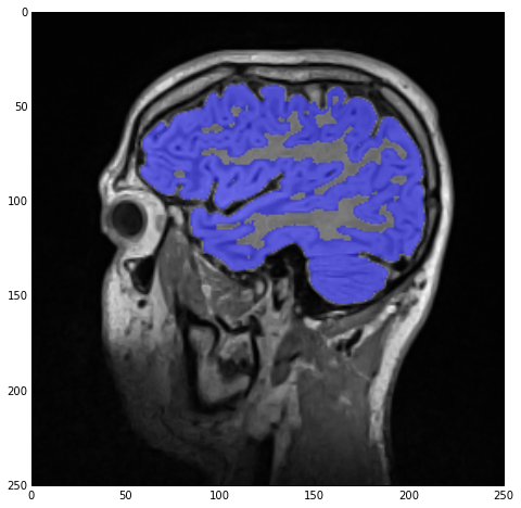
sitk_show(SimpleITK.LabelOverlay(imgSmoothInt, imgLabels))
with the result being stored under imgLabels:
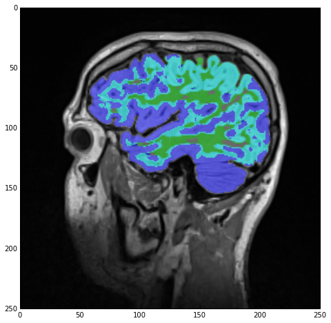
However, note the cyan-colored label! Those are regions ‘claimed’ by both the white-matter and gray-matter labels due to our lazy segmentation. As we can see, the majority of those regions should actually be part of the gray matter so let’s do exactly that:
imgMask= imgWhiteMatterNoHoles/labelWhiteMatter * imgGrayMatterNoHoles/labelGrayMatter
imgWhiteMatterNoHoles -= imgMask*labelWhiteMatter
imgLabels = imgWhiteMatterNoHoles + imgGrayMatterNoHoles
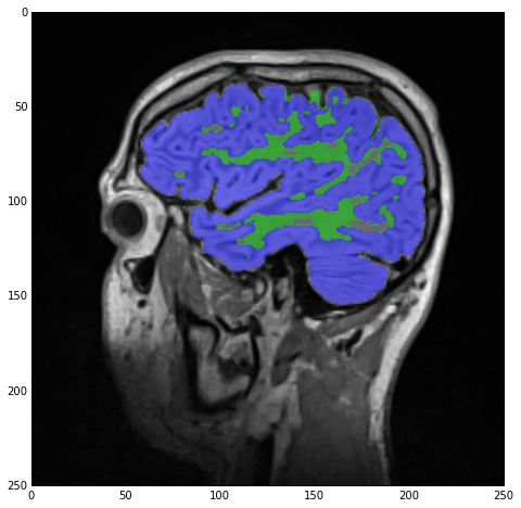
sitk_show(SimpleITK.LabelOverlay(imgSmoothInt, imgLabels))
Firstly, we create imgMask which will be a ‘boolean’ image containing only the common regions of the two labels. We achieve that by firstly dividing the respective labels by their label index value, therefore switching their values to 1s and 0s.
Then we just multiply those common regions by labelWhiteMatter to switch its values back to those of the white-matter label, and subtract the result from imgWhiteMatterNoHoles (therefore letting imgGrayMatterNoHoles keep those regions).
Finally, we recreate imgLabels by adding imgWhiteMatterNoHoles and imgGrayMatterNoHoles and the result of sitk_show can be seen below:
The above code was mostly meant to show you the power of the overloaded operators and their effect on image data. There are many, more appropriate, filters in SimpleITK to do the above but I just wanted you to see how easy it is to play around with your images.
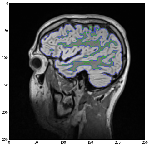
As a final treat lets visualize the two labels as edge-only contours using the LabelContourImageFilter class.
sitk_show(SimpleITK.LabelOverlay(imgSmoothInt, SimpleITK.LabelContour(imgLabels)))
Outro
As you can see, my segmentation was by no means perfect. Far from it actually as the gray matter unjustly claimed regions of white matter in nooks and crannies. However, a perfect segmentation wasn’t the point of this post.
Image segmentation is inherently interactive and repetitive, which is why there are dozens of applications out there neatly wrapping functionality such as what we saw today in a GUI. If you want to perform ‘proper’ segmentations of medical image data then take a look at applications like TurtleSeg, ITK-SNAP, MITK, etc etc. Google’s your friend :).
The point of this post, however, was to introduce you to SimpleITK, a truly simplified interface to a very powerful library. As I said in the intro, I barely scraped the surface here and there’s still a lot of very interesting functionality to explore.
Before I close, I’d like to note that going from a label-field, such as the one we saw above, to a 3D surface is rather easy. All one would need to do is segment the full 3D image data and then use a surface extraction algorithm on each label much like what I presented in this past post about surface extraction.
Links & Resources
Material
Here’s the material used in this post:
- IPython Notebook showing the presented process.
- MRI Dataset of my head on which segmentation was performed.
- Alternative IPython Notebook repeating the segmentation process but using different filters in an attempt to expose you to different SimpleITK functionality.
- SimpleITK .egg for Anaconda Python 2.7 on Windows x64
- SimpleITK .egg for Anaconda Python 2.7 on Linux x64
- SimpleITK .egg for Anaconda Python 2.7 on Mac OSX x64
See also
Check out these past posts which were used and referenced today or are relevant to this post:
- Anaconda: The crème de la crème of Python distros
- IPython Notebook & VTK
- NumPy to VTK: Converting your NumPy arrays to VTK arrays and files
- DICOM in Python: Importing medical image data into NumPy with PyDICOM and VTK
- Surface Extraction: Creating a mesh from pixel-data using Python and VTK
SimpleITK
If you want to read up on SimpleITK then check out the following resources:
– The Design of SimpleITK: A freely available article by Bradley Lowekamp on SimpleITK and a rather good starting point.
– SimpleITK Tutorial for MICCAI 2011: A GitHub repo containing the material for a SimpleITK tutorial presented at MICCAI 2011. Its quite a good introduction and you can find the presentation as a .pdf here.
– SimpleITK Notebooks: A collection of IPython Notebooks showcasing different features of SimpleITK. You might also want to check the GitHub repo of the above page which contains the demo-data and some extra notebooks. However, keep in mind that some of the code, particularly that dealing with fancy IPython widget functionality, won’t work straight out. Nonetheless, its the best resource out there. Another nice IPython Notebook entitled ‘SimpleITK Image Filtering Tutorial’ can be found here.
– SimpleITK Examples: A small number of basic examples in C++ and Python which showcases some of the SimpleITK functionality. The number of demonstrated classes, however, is rather small.
– Should the above not prove sufficient, your best bet is to read about ITK itself. The 4th edition of the two ‘ITK Software Guide’ books, namely ‘The ITK Software Guide Book 1: Introduction and Development Guidelines’ and ‘The ITK Software Guide Book 2: Design and Functionality’, are actually freely available as `.pdf` files and provide a rather in-depth overview of the library. Lastly, there are many more examples on ITK than on SimpleITK and through those you can find out about many useful classes and algorithms implemented in ITK and which are wrapped in SimpleITK.

Hi Adamos and many thanks for your articles on segmentation!
I’ll be laconic…I want to obtain the boundaries of hip and femur in a CT dataset for total hip arthoplasty…automatically. I’m inclined to use SimpleITK. Do you reckon it’s the right tool?
Efharisto
LikeLike
Hey Saki 🙂
Yeah I think your problem is as easy as it gets in terms of segmentation. Firstly, take a look at the previous post about surface extraction where I talk about Hounsfield units in CT and thresholding. If anything, thresholding is even easier with SimpleITK since you can simply write something like this:
imgCtThresholded = imgCtOriginal > ThresholdBones
and you’ll get a boolean mask with the bones automatically segmented (assuming you chose a decent threshold). I haven’t checked whether SimpleITK’s GDCM automatically rescales CT data (again, check the aforementioned post) but you should make sure the data is rescaled prior to thresholding them.
Then, assuming that by ‘boundaries’ you mean the edges of the bone-structures, you can simply use the ‘SimpleITK. CannyEdgeDetectionImageFilter’ or rather the direct function call ‘SimpleITK.CannyEdgeDetection’
I think that between SimpleITK and VTK you can easily segment the bones out and even create nice 3D models through surface extraction 🙂
Lemme know if you run into trouble
Cheers,
Adam
PS. You could always use OpenCV instead of SimpleITK if you’re more comfortable with that, it has a lot of SimpleITK’s functionality, but I don’t think it natively supports DICOM files (thus you’d have to first load the DICOM files through PyDicom or VTK
LikeLike
Hi Adam,
many-many thanks for you reply. I will try out your advice and let you know how it went. Once again, indebted 🙂
LikeLike
Haha, my pleasure :D. Good luck with it and don’t hesitate to drop me a line if you run into a brick wall 🙂
LikeLike
Pingback: Multi-Modal Image Segmentation with Python & SimpleITK | PyScience
Hi Adam, I hit the wall:D
to summarize: it works pretty well:) I haven’t tried many datasets yet but I just thresholded the images (SimpleITK’s GDCM automatically rescales CT data – check) using:
imgCtThresholded = 380 > imgOriginal > 420
(I tried other thresholding functions too but results were inferior). I then used
GradientMagnitudeRecursiveGaussian(imgCtThresholded)
to obtain the boundaries…that blurs the image a bit but tends to connect some of the regions where the bone is faint and since I’m not too bothered for slight deviations from the original geometry it’s fine. However some regions, where bone outlines are really faint, are thresholded out and are thus not detected. I tried smaller values to include them but that made a mess.
The CannyEdgeDetectionImageFilter was having difficulties with unconnected regions and produced more boundaries instead (as was the case with ZeroCrossingBasedEdgeDetection).
The function call SobelEdgeDetection also gave good results but again leaving the faint bone boundaries unconnected.
As it seems to me that the reason I can’t detect faint bone boundaries is that I threshold them out, I was thinking whether there is a ‘sharpen’ function I could use to enchance their intensity
before thresholding them. Do you have any suggestions?
Many thanks in advance,
Saki
LikeLike
Hey Saki!
Its good to hear from you again, seems you got down to it pretty fast :).
Of course it ain’t particularly easy for me to suggest foolproof approaches, especially since I can’t play around with the DICOM data but here are a couple comments/ideas:
– You say you threshold with “imgCtThresholded = 380 > imgOriginal > 420”. May I ask what the the “380 > imgOriginal” is there for?
– Did you try applying any image-smoothing prior to thresholding? Faint regions may then pick up intensity from the surrounding ones and allow for easier segmentation. Median filters typically preserve the edges and enhance the inner regions so it might do the trick. Otherwise, averaging filters should probably boost those regions as well.
– You could try the ConfidenceConnected region-grower (upon smoothing) on the non-thresholded image and see if it’ll pick-up those faint connecting regions the thresholds miss. Heck, you could probably use the results of the thresholding, erode them severely into smaller regions, and use those regions as seeds for the region-growing. I haven’t tried it yet but it might work 🙂
If none of the above work perhaps you could send me a copy of the notebook and dataset and I could give it a go but i can’t promise a speedy resolution cause things have been getting rather hectic with work 🙂
Let me know how it turns out! Especially if something works I’d love to hear the trick (I’m sure people run into issues like yours all the time and posterity may thank you for detailing the solution) 😀
Cheers!
Adam
LikeLike
Hi Adam,
thanks again for your help and insight! If anyone needs to be thanked by posterity (and present troubled scientists) it’s certainly you and this blog:) The reason I’m dwelling into this is THA and there’s no way (as I’m not an expert in image processing) I could have start playing with datasets to obtain a patient’s geometry had I not stumbled across your blog (SimpleITK’s documentation is not that impressive as you’ve pointed out).
Now regarding your comments:
– I was using the 380 > ImgOriginal 380 definition but I didn’t get an error either (I had the operator wrong in my previous post, sorry:)).
– I did try smoothing but I only used some Gaussian filters which at first glance seem not to preserve the edges. I will try median and averaging filters as well and let you know how it went.
– I gave ConfidenceConnected a try but my seed selection was problematic. As I want to do the process automatically, I only chose a seed on the bone for the first DICOM. But my definition was static (didn’t change when I loaded the next image), and that’s probably why it didn’t give great results. I really like your idea about erosion of the thresholded areas followed by region-growing though…I will try it out and bug you again to let you know how it went.
Cheers,
Saki
LikeLike
Haha thanks for the kind words :). I pretty much owe all the coding I know to the kindness of bloggers and book authors so I just thought I’d give a lil’ back :D.
Give the whole median filtering and ConfidenceConnected approach a go. Please let me know how it goes 🙂
Alternatively I’d suggest you take a look at what other researchers are doing in the field of automatic bone segmentation with CT and steal their ideas (or find out what didn’t work). Chances are that the filters and approaches they employ exist in SimpleITK. A quick search yielded these two seemingly interesting papers:
http://ieeexplore.ieee.org/xpl/login.jsp?tp=&arnumber=1207394
http://ieeexplore.ieee.org/xpl/login.jsp?tp=&arnumber=1263905
Good luck and I’m sorry I can’t offer more specific help but I’m not much of a segmentation expert (in fact I pretty much hate segmentation)
Cheers,
Adam
LikeLike
Hi Adam,
it took me a while but I’m finally back to report on my experience:) My problem in sort was that due to osteoporosis the reconstructed surface had holes and unconnected regions. I tried multiple filters and alternative approaches for bone reconstruction but to no avail. Finally I solved it in the following way:
1) Get a first geometry using only VTK as you describe here https://pyscience.wordpress.com/2014/09/11/surface-extraction-creating-a-mesh-from-pixel-data-using-python-and-vtk/ (also used some filtering, mesh clean-up, etc.)
2) Import the stl in CATIA and get cross -sections of the bone in the z-direction. Use them to obtain intersection curves (essentially the same picture as the original DICOM images but now described by NURBS.
3) Get the points on those curves and run an AlphaShape detection on them. This is the tricky part: where you have holes you get a closed spline shaped like a C. By varying the Alpha-value it’s possible to obtain a new curve that is something between the concave hull (which would give a C again) and the convex hull (which would exclude points on the boundary and give a bigger surface area). I used CGAL for the AlphaShape algorithm.
4) Using the new splines and a bit of clever CAD modeling with reference planes and “near” operations we can reconstruct the geometry with no holes as we need it for CAE simulation (Finally:) I was beginning to think that I’ll age over this!)
Once again I’d like to thank you for your help and your great posts. All the best!
Saki
LikeLiked by 1 person
Hello,
i try follow your entry, but in my python appears this message: “NameError: name ‘sitk_show’ is not defined”
I have installed Anaconda-2.1.0-Windows-x86_64 and your SimpleITK-0.8.0.post47-py2.7-win-amd64 however python can’t recognize this function
I thank you in advance for the attention you will pay to this problem.
LikeLike
Hi Enrique :). Well the ‘sitk_show’ function is an auxiliary function I’ve defined within this post’s IPython notebook for the purposes of my demonstration. Its not defined within SimpleITK. Check the beginning of this post’s notebook and you’ll find the function 🙂
LikeLike
Oh my god! 🙂 Thank you, but… i’m begginer in python and i don’t known the method to call this function, I save a file with name “sitk_show.py” to include function sitk_show
LikeLike
Well, I resolve by myself… however, now show this error “TypeError: Invalid dimensions for image data” The image is dicom for RMI
LikeLike
Hi Enrique, sorry I went to sleep after replying to your first comment (it was already 1am in Australia). From the sounds of it you were working straight into the terminal? Otherwise you could just start a new notebook and copy-paste the helper-functions.
Now for the error you’re getting. I can’t say I know what RMI stands for but that doesn’t really matter. Can you tell me what kinda of DICOM data you’re dealing with?
Also, which command is it that throws that error? I’ve seen that error a couple times when someone’s trying to display a full 3D image instead of a 2D slice but I’m not sure what’s going off in your code.
I’m afraid that unless you give me more info, or show me your code, I can’t quite help you
LikeLike
Pingback: Volume Rendering with Python and VTK | PyScience
Hi Adamos,
Thanks for your article: unfortunately I’m still running into the dreaded “Fatal Python error: PyThreadState_Get: no current thread”, despite following your instructions (OSX, your .egg, fresh Anaconda py27 environment). Any ideas, before I try to build it myself from scratch?
Richard
LikeLike
Hi Richard,
I was afraid some people may have issues with the OSX egg but you’re the first one to report anything positive/negative on it. Bums me out :). Could you please try the following? Go into your terminal and run the following for me:
otool -L /anaconda/envs/py27/lib/python2.7/site-packages/SimpleITK-0.8.0.post48-py2.7-macosx-10.5-x86_64.egg/SimpleITK/_SimpleITK.so
which on my machine gives the following output:
/anaconda/envs/py27/lib/libpython2.7.dylib (compatibility version 2.7.0, current version 2.7.0)

/System/Library/Frameworks/CoreFoundation.framework/Versions/A/CoreFoundation (compatibility version 150.0.0, current version 855.17.0)

/usr/lib/libSystem.B.dylib (compatibility version 1.0.0, current version 1197.1.1)

/usr/lib/libc++.1.dylib (compatibility version 1.0.0, current version 120.0.0)
Please paste your output in a comment-reply.
You see, compiling a project on OSX with CMake and trying to link against a non-vanilla Python is a hassle. Not only do you have to explicitly give CMake the paths to the non-vanilla Python interpreter, headers, and library, but CMake ends up not linking properly to that library but rather referencing the system Python. Its entirely a CMake issue and it has been known for a while. In order to make my compilation/egg work I ‘hacked’ the correct Python library into the .so file as such:
sudo install_name_tool -change libpython2.7.dylib /anaconda/envs/py27/lib/libpython2.7.dylib /anaconda/envs/py27/lib/python2.7/site-packages/SimpleITK-0.8.0.post48-py2.7-macosx-10.5-x86_64.egg/SimpleITK/_SimpleITK.so
As you can see I ‘hardcoded’ the library reference to ‘/anaconda/envs/py27/lib/libpython2.7.dylib’. If your anaconda isn’t installed under the same path or if your conda environment isn’t named ‘py27’ then chances are it won’t work.
Could you give me your paths? Are they matching? If they do and it still didn’t work then I’d be happy to provide you with instructions on how to build SimpleITK yourself 🙂
Cheers!
Adam
LikeLike
Hi Adam
I get
/anaconda/envs/py27/lib/libpython2.7.dylib (compatibility version 2.7.0, current version 2.7.0)/System/Library/Frameworks/CoreFoundation.framework/Versions/A/CoreFoundation (compatibility version 150.0.0, current version 855.17.0)
/usr/lib/libSystem.B.dylib (compatibility version 1.0.0, current version 1197.1.1)
/usr/lib/libc++.1.dylib (compatibility version 1.0.0, current version 120.0.0)
which is the same as you. If you could spare the time to show me how to build SimpleITK myself, I’d really appreciate it!
Cheers,
Richard
LikeLike
Hi Richard,
Its really weird it doesn’t work then, is your ‘libpython2.7.dylib’ file located at that path then?
Anyway, here’s how you should go about building SimpleITK against your Anaconda Python:
0) Activate your preferred conda environment. I will assume its called ‘py27’ but be careful to amend appropriately and activate through ‘source activate py27’
1) Go to this link: http://www.itk.org/Wiki/SimpleITK/GettingStarted#Build_It_Yourself and take a look at the instructions first.
2) Make sure you have CMake installed (I used the 2.8.12 version)
3) Make sure you have the gcc and g++ compilers installed. I had XCode installed which comes with those. Test that in your terminal through ‘gcc -v’ and ‘g++ -v’
4) In your terminal ‘cd’ to some directory where you want to download the code.
5) Clone the SimpleITK Git repo through ‘git clone http://itk.org/SimpleITK.git‘
6) Once checkout is complete type ‘cd SimpleITK’ so you can go into the newly created directory
7) Switch to the release branch as you don’t want to build whatever buggy version lives in the master branch by entering ‘git checkout release’
8) Go up one directory through ‘cd ..’
9) Create a new directory called ‘SimpleITK-build’ by entering ‘mkdir SimpleITK-build’. Now this directory should be alongside the ‘SimpleITK’ directory containing the source code
10) Go into the ‘SimpleITK-build’ directory by entering ‘cd SimpleITK-build’
11) launch the CMake GUI tool using the ‘SuperBuild’ in the source directory as such ‘cmake-gui ../SimpleITK/SuperBuild’
12) Now you should get the CMake window. Make sure the ‘Advanced’ checkbox is enabled
13) Hit the ‘Configure’ button and choose ‘Native Unix Makefiles’ (or sth like that)
14) Now we have to configure the build to work with Anaconda Python:
14a) Use the ‘Search:’ field and enter ‘WRAP’. Out of the 8 entries or so disable everything except ‘WRAP_PYTHON’
14b) Hit ‘Configure’ again to update the entries
14c) Search for ‘PYTHON’
14d) Now we have to set the appropriate paths to the Python interpreter, headers, and dylib. This is important so be careful. Check exactly where your conda environment resides. Mine was called ‘py27’ and the ‘anaconda’ folder was located under the root so my environment directory was ‘/anaconda/envs/py27/’. Make sure to amend the paths I will use to match yours!
14e) Set the ‘PYTHON_EXECUTABLE’ to ‘/anaconda/envs/py27/bin/python’ (again, amend as necessary)
14f) Set ‘PYTHON_INCLUDE_DIR’ to ‘/anaconda/envs/py27/include/python2.7’ (amend)
14g) Set ‘PYTHON_LIBRARY’ to ‘/anaconda/envs/py27/lib/libpython2.7.dylib’
15) Now delete whatever you have written in the ‘Search’ field to see all entries
16) Make sure the ‘BUILD_EXAMPLES’, ‘BUILD_SHARED_LIBS’, and ‘BUILD_TESTING’ checkboxed entries are all off.
17) Now all the rest should be fine and you should be fine. Hit ‘Configure’ again and then hit ‘Generate’
18) If you get any errors at this point then sth is off with your environment and I would suggest your reinstall/update your XCode. Let me know if any particular error shows up here. If it does make sure the Python paths you set are correct!
19) Close CMake and go back to the terminal
20) Assuming you’re still under the ‘SimpleITK-build’ directory all you need to do is build the project. Enter ‘make’ or (if you have multiple cores) ‘make -j 4’ (for quad-core) to run the build on multi-core. It’ll be faster
21) Once the build completes you should be almost ready to go. If any errors occurred then we’ll have to go over them in detail.
22) While still in the ‘SimpleITK-build’ directory run the following to test the generated ‘so’ file: ‘otool -L SimpleITK-build/Wrapping/_SimpleITK.so’. Should CMake have screwed up as it tends to do on OSX it should tell you that its linking against the system python and not Anaconda.
23) Let’s install SimpleITK anyway and then fix it. Being in the ‘SimpleITK-build’ directory (next to the freshly checked out copy of SimpleITK in the ‘SimpleITK’ dir) cd into the ‘Wrapping’ dir as such ‘cd SimpleITK-build/Wrapping’
24) Install the package into your conda environment (which we activate in step No. 0) through ‘python PythonPackage/setup.py install’
25) Now if you did everything right you should be able to start an ipython session (‘ipython’ command in terminal) and try to ‘import SimpleITK’. You should get that horrible error again.
26) Now you have to apply that nifty little hack we discussed and hardcode the correct library. Exit the IPython session (Ctrl+D) and get back into the terminal session. We can now hack the correct library reference into the copy of the SimpleITK .so file that got installed into your conda environment. This is done with the following command:
sudo install_name_tool -change libpython2.7.dylib /anaconda/envs/py27/lib/libpython2.7.dylib /anaconda/envs/py27/lib/python2.7/site-packages/SimpleITK-0.8.0.post48-py2.7-macosx-10.5-x86_64.egg/SimpleITK/_SimpleITK.so
HOWEVER! Be careful mate :). Make sure that (1) ‘/anaconda/envs/py27/lib/libpython2.7.dylib’ is correct and that the ‘_SimpleITK.so’ file is indeed under ‘/anaconda/envs/py27/lib/python2.7/site-packages/SimpleITK-0.8.0.post48-py2.7-macosx-10.5-x86_64.egg/SimpleITK/_SimpleITK.so’. Alternatively, amend the paths correctly. Of course, you can fix the .so file generated by the build process so you can later on redistribute but that’s up to you :).
Once you run the above command (successfully) you can try to start IPython again and ‘import SimpleITK’ and it should go through fine. If not lemme know and I’ll see what I can do 🙂
Caution: I wrote these instructions largely from memory but they should be mostly correct. Please go through the steps carefully.
Hope this helps
Cheers,
Adam
LikeLike
Hi Adam. Great job. I have a question. I have a 3d dicom file and I want either to separate it in 2d slices and process it as you describe here or to process it as it is in the whole volume. How can I do one of the two? Thanks for your help.
LikeLike
hi there, I’ve never seen a 3D DICOM file! Can you even read that with PyDICOM/VTK/SimpleITK? If you can then all you need to do is read it into a 3D numpy array really. From there its easy to just create SimpleITK images and work in a multi-slice 2D manner or simply a volumetric 3D manner. I’m not sure what your issue is so you might need to clarify 🙂
LikeLike
My image is a dicom file of an MRA image of 128 slices.
First of all thanks a lot for your help. What I am doing is:
image=sitk.ReadImage(“myimage.dcm”)
a=sitk.GetArrayFromImage(image)
imgOriginal = a[42,:,:] –pick a slice
imgSmooth = SimpleITK.CurvatureFlow(image1=imgOriginal,
timeStep=0.125,
numberOfIterations=5)
and I am having this error:
TypeError: in method ‘CurvatureFlow’, argument 1 of type ‘itk::simple::Image const &’
Thanks a lot. 🙂
LikeLike
Hmm your code looks entirely fine really and the error is weird. All I can think of is that you have some issue with the image you’re feeding to the algorithm. Are your pixel values of float/integer type? Some of the SimpleITK filters have restrictions in that they only work with integers or floats. Did you try casting your image to another type prior to feeding it to the CurvatureFlow filter?
Unless your image is part of a confidential dataset perhaps you could send me a subset and I could give it a go myself cause I can’t tell what might be wrong based on the snippet. My email is kyriakou.adamos at gmail. Perhaps I can help you thusly 😀
LikeLike
Hi Adam. Thanks for the forum. it is really helpful. I am a beginner for simpleITK and python.Actually, I have lung DICOM slices on which I want to apply segmentation as saki explained in his comment. I tried the same method to segment the lung region but I am getting black image. your help would be appreciable… Thanks:)
LikeLike
lungs should be easy if you have CT (due to the fact that they have very low Hounsfield units and should be very easily discernible) but I can’t quite know what might be wrong with your process for you to get a black/blank image. I can’t promise I’ll do it any time soon but if you detail your issue(s) and send me a subset of the DICOM dataset I can try and take a looksie. my email’s kyriakou.adamos at gmail
LikeLike
Hi Adam, As many of the other commenters have relayed, THANK YOU, for sharing your deciphering of SimpleITK for us. While very powerful and convenient at times, I’ve been relying on sheer luck when using sitk in the past.
I’ve hit a small problem with the VotingBinaryHoleFilling I’m hoping you might be able to shed some light on..
I’ve tried setting up a small program to do the following
img = imgDataset
rad = [x,y,z] (some input radius in three dimensions)
seg = sitk.VotingBinaryHoleFilling(img,radius=rad,majorityThreshold=1,backgroundValue=0,foregroundValue=1)
I’ve tried setting rad to [10,10,10] or [10]*3 (per your example). But every time I get the following:
seg = sitk.VotingBinaryHoleFilling(img,radius=rad,majorityThreshold=1,backgroundValue=0,foregroundValue=1)
File “/hpc/packages/minerva-common/py_packages/2.7/lib/python2.7/site-packages/SimpleITK-0.8.1-py2.7-linux-x86_64.egg/SimpleITK/SimpleITK.py”, line 40055, in VotingBinaryHoleFilling
return _SimpleITK.VotingBinaryHoleFilling(*args, **kwargs)
TypeError: in method ‘VotingBinaryHoleFilling’, argument 2 of type ‘std::vector< unsigned int,std::allocator > const &’
Do you have an idea of what I might be doing wrong? Does the input variable need some kind of datatype definition?
Thanks!
Brett
LikeLike
Holy crap how did I miss this! Its been a bloody month! Really sorry Brett, hope you’ve figured it out already 😛
I don’t see you doing anything wrong and indeed the radius is supposed to be a list which gets casted to a vector internally. As you said I’m doing exactly the same thing.
If by some freak coincidence you haven’t sorted it out yet you mind sending a sample of the dataset you’re using? I can’t seem to reproduce your error
LikeLike
No worries!
I did figure it out. I’m still a newbie to python and coding in general so it turns out I just needed to define my rad variable properly. I was trying to define it as a string, oops!
LikeLike
Whaa? I didn’t see any quotes around it in your snippet. I’m glad you figured it out and sorry once more
LikeLike
Hello Adam,
Surely, I did not know of the existence of such a nice library. Some campaign is required to ensure all its abilities are documented.
Thank you for the effort.
Because of its ability to read DICOMs, I wanted to use SimpleITK to read and smoothing DICOM files before using them in self organising map (SOM) architecture. For instance: following this tutorial up to to the creation of imgSmooth, then use imgSmooth as the input to the SOM, which requires the input to be:
pixels = reshape(imgSmooth,(imgSmooth.shape[0]*imgSmooth.shape[1],3))
Then pixels is fed into the SOM.
unfortunately, this fires an “AttributeError: type object ‘object’ has no attribute ‘__getattr__”
These are the details of the error:
In [16]: runfile(‘/home/john/Documents/images2use/somImageEdits-ITK.py’, wdir=’/home/john/Documents/images2use’)
Traceback (most recent call last):
File “”, line 1, in
runfile(‘/home/john/Documents/images2use/somImageEdits-ITK.py’, wdir=’/home/john/Documents/images2use’)
File “/home/john/anaconda/lib/python2.7/site-packages/spyderlib/widgets/externalshell/sitecustomize.py”, line 685, in runfile
execfile(filename, namespace)
File “/home/john/anaconda/lib/python2.7/site-packages/spyderlib/widgets/externalshell/sitecustomize.py”, line 78, in execfile
builtins.execfile(filename, *where)
File “/home/john/Documents/images2use/somImageEdits-ITK.py”, line 71, in
pixels = reshape(imgSmooth,(imgSmooth.shape[0]*imgSmooth.shape[1],3))
File “/home/john/anaconda/lib/python2.7/site-packages/SimpleITK-0.9.1-py2.7-linux-x86_64.egg/SimpleITK/SimpleITK.py”, line 3579, in
__getattr__ = lambda self, name: _swig_getattr(self, Image, name)
File “/home/john/anaconda/lib/python2.7/site-packages/SimpleITK-0.9.1-py2.7-linux-x86_64.egg/SimpleITK/SimpleITK.py”, line 74, in _swig_getattr
return _swig_getattr_nondynamic(self, class_type, name, 0)
File “/home/john/anaconda/lib/python2.7/site-packages/SimpleITK-0.9.1-py2.7-linux-x86_64.egg/SimpleITK/SimpleITK.py”, line 69, in _swig_getattr_nondynamic
return object.__getattr__(self, name)
AttributeError: type object ‘object’ has no attribute ‘__getattr__
Any idea how to go about such?
Thanks.
LikeLike
Hey John, I think the error is caused by the fact that you’re using the ‘shape’ attribute, on a SimpleITK.Image object which is not a numpy array and thus has no ‘shape’ attribute. You might be thinking of the ‘SimpleITK.Image.GetSize’ method
LikeLike
Hello Adamos,
I have recently been following your blog posts, specifically, I was reading your post about segmentation with Python & Simple ITK. I have come across a problem that might benefit from your expertise: I want to segment the skin from an MRI (.nii) image. i saw in the example you are using a CT and thresholding with HU, but with MRI what would be the best way to threshold?
Any ideas would be most appreciated!
Thank you.
LikeLike
For anyone else wondering I’ve already replied to the above comment via email with the following reply:
Hi Parikshat,
I might have to disappoint you here, I’ve worked with a lot of segmentation experts in my last job and they all said that segmenting the skin cannot be easily done with either MRI or CT images. I was always told that skin is tricky cause it ‘merges’ with the fat and is not clearly visible in most modalities.
As such I was always advised to segment the fat (as the subcutaneous fat or SAT is the tissue physically closest to the skin) and then perform a dilation operation by X pixels where X will be calculated based on your image resolution and the typical skin thickness at the are (for example if your image has a spacing of 0.5mm and you want 3mm of skin you just dilate by 6 pixels). You can do that by:
1) First segmenting the SAT into its own segmentation label (lets call it L_fat)
2) Dilating that label by X pixels into another label using this filter http://www.itk.org/SimpleITKDoxygen/html/classitk_1_1simple_1_1BinaryDilateImageFilter.html (lets call this label L_fat_dilated)
3) Creating the skin label by subtracting L_fat from L_fat_dilated and creating the L_skin label
That’s all I can do I’m afraid, let me know if you find a better way of doing it but that’s what all the segmentation people used to tell me 🙂
Hope this helps
Best,
Adam
LikeLike
Hi Adamos,
Do you know of any way to determine which index of of my CT array represents to which view, i.e., Sagittal, or Axial, or Frontal.
For example, in your case, imgOriginal[:, :, idxSlice], the third index, gives the Sagittal view (if I am not wrong). In my case it was showing the Axial slice. Is there a way to determine which index refers to which view from the DICOM files, or do I need to do it manually for each of my CT volumes ?
Thanks in advance.
LikeLike
While I haven’t looked into it myself some googling indicates that DICOM orientation is well defined in respect to the patient and stated in the metadata. Please see here:
http://dicomiseasy.blogspot.com.au/2013/06/getting-oriented-using-image-plane.html?m=1
LikeLike
Hi Adam,
Thank you for your great tutorials and introductions.
I followed this one step-by-step (I am a complete pyhton beginner) and successfully plotted my first CT image! Yay. (It’s a plastic tube filled with water)
Then I’ve tried to automatically calculate pixels for a seed list, but somehow SimpleITK doesn’t accept them. If I manually type in coordinates eg. [(12,14),(14,14)] , it works. But if I use numpy to create an array with pixel coordinates, which I then change into a list of tuples it doesn’t..
Could you maybe please have a look at this error-message? I showed it to friend that knows python, but she got pretty confused trying to understand SimpleITK quickly.
https://github.com/cyberspeck/mrt-for-rt/blob/master/develop/2016-07-13-db_SimpleITK-2D.ipynb
Thank you.
david
LikeLike
Hi David, I’m really sorry for the super-late reply. I was abroad till a couple days back and during the trip my phone decided to go for a swim and was never seen again, so I was off the grid.
I tried checking the notebook but the link 404’ed. I’d be happy to take a look if you can toss me an updated link (unless of course you’ve solved it during my absence).
cheers,
adam
LikeLike
Dear Adam,
I haven’t found a solution yet. I guess the problem has something to do with C++ using different data types than pyhton, but honestly I don’t know how to tackle this.
Instead I spend my time working on different aspects of my project.
I’d be very happy, if you could have a look:
https://github.com/cyberspeck/mri-for-rt/blob/master/develop/2016-07-13-db_SimpleITK-2D_problem-automated-seedlist.ipynb
Thank you for your time.
Cheers, david
LikeLike
Hey David, just tried it out.
As I thought the issue comes down to versioning, i.e., it works perfectly fine on Python 2 (specifically Python 2.7.12 :: Anaconda 2.1.0 (x86_64) and SimpleITK (0.8.0.post48)).
Generally speaking packages like VTK and SimpleITK do work best on Python 2 so unless there’s a very good reason for it I’d stick with that (personally I didn’t even know that SimpleITK is supposed to support Py3).
Would that do it for you? Can you use py2 or are you stuck?
cheers,
adam
LikeLike
Dear Adam,
I finally got myself to create a virtual environment using anaconda. For this I first had to install conda, thought ^^.
It seems to work, just as you said. Luckily my code seems to be running smoothly, too. No errors coming up after switching from python3.4 to python2.7
Thanks again for your help.
Wishing you a wonderful Christmas,
david
LikeLike
Awesome David good to hear it! Py3 just isn’t quite there for some of those packages but hopefully you’ll still be able to get your stuff done :).
Enjoy the xmas break!
LikeLike
Hi Adam! Thank you for lovely tutorials! Everything was fine until vtk post. With SimpleITK I get the following error and it has been driving me crazy for almost a day now. This is what the error says when I import SimpleITK. As you might know, anaconda now has the SimpleITK package which I can install simply by conda install –channel SimpleITK SimpleITK
Error: Traceback (most recent call last):
File “”, line 1, in
runfile(‘C:/Users/SidhartaG/.spyder2/temp.py’, wdir=’C:/Users/SidhartaG/.spyder2′)
File “C:\Users\SidhartaG\Anaconda2\lib\site-packages\spyderlib\widgets\externalshell\sitecustomize.py”, line 699, in runfile
execfile(filename, namespace)
File “C:\Users\SidhartaG\Anaconda2\lib\site-packages\spyderlib\widgets\externalshell\sitecustomize.py”, line 74, in execfile
exec(compile(scripttext, filename, ‘exec’), glob, loc)
File “C:/Users/SidhartaG/.spyder2/temp.py”, line 7, in
import SimpleITK
File “C:\Users\SidhartaG\AppData\Roaming\Python\Python27\site-packages\SimpleITK\__init__.py”, line 1, in
from .SimpleITK import *
File “C:\Users\SidhartaG\AppData\Roaming\Python\Python27\site-packages\SimpleITK\SimpleITK.py”, line 28, in
_SimpleITK = swig_import_helper()
File “C:\Users\SidhartaG\AppData\Roaming\Python\Python27\site-packages\SimpleITK\SimpleITK.py”, line 24, in swig_import_helper
_mod = imp.load_module(‘_SimpleITK’, fp, pathname, description)
ImportError: DLL load failed: %1 is not a valid Win32 application.
Kindly look into it and help if possible. I will just reference some solutions which I tried and didn’t work:
[1] (http://stackoverflow.com/questions/33455239/conda-update-all-importerror-dll-load-failed-1-is-not-a-valid-win32-appl)
[2] (http://stackoverflow.com/questions/4676433/solving-dll-load-failed-1-is-not-a-valid-win32-application-for-pygame)
I am using the latest Anaconda 4.1 64-bit version for my 64-bit system on Windows.
LikeLike
Hey Sidh, yikes the versions are moving crazy fast! I’m currently using Anaconda 2.1.0 (x86_64) and SimpleITK v0.8.0 which is the one I compiled when I made the posts.
You may want to try these particular versions cause I know they work on Windows x64 cause the above definitely seems like a version issue.
Do you get the same error when importing SimpleITK outside of Spyder, e.g., from the IPython console? Which SimpleITK version did you install (I can see multiple Python 2.7 versions here: https://conda.anaconda.org/simpleitk/win-64) ?
LikeLike
Thank you for your reply. I fixed it. It was a python problem. I had to install everything with 32 bit and used some whl from goelke. Thanks a lot.
LikeLike
Hi Adam! I’m commenting here again because I ran into a problem. I have programmed before majorly in C++ and little of Java so ITK codes are something I can understand with no issues. I have been working on segmenting Lungs from a CT in python ( I am required to do it in python). So I do an automatic seed point detection to find the trachea/airway and remove it from the segmentation. The trachea is usually present predominantly in either the first 25 or the last 25 slices of the scan. So I zeroed in on looking for the seed point in these slices. Normally, I have a few constraints:
Look for a area (between 50sq.mm and 1225 sq.mm) which is not more than 0.3 x,y of the dimensions away from the center of the slice and an average HU less than -950. With this, I can find the seed point and do a basic region growing to find the trachea. Then using the same point, perform thresholding and remove the trachea from it. This is the state of the art I’m trying to implement so that I can adjust it with some of my own work which best suites our dataset.
Now the issue is, how do i find the area of the region? I know I can do basic thresholding and do a blob detection (in Matlab it also gives me area directly) and then find the point in the area with the lowest HU. How can I do it in ITK?
I tried using CCAFilter, I get components but I don’t find any ‘clear’ functions in the library to extract just one label. There is this GetBoundingbox() function which gives me two coordinates in the area with the maximum euclidean distance, but I don’t think I can directly use (x1 – x2)*(y1 – y2) to get the area in mm.
Thanks in advance for your help!
LikeLike
Hey Sidh! This might not be the cerebral approach you may have wanted but you could simply count the number of pixels in the segmented label. Now I’m on the phone and can’t tell you how to do so in ITK off the top of my head but you could simply convert to NumPy, do a simple Boolean mask on the array, such as img==label_index and do a sum on the result. Then you already know the pixel spacing which I assume is homogeneous across the image so just multiply the previous result with the area of a single pixel. Same approach of course can be followed for volume 🙂
LikeLike
Hey Adam, Thanks for the answer. At the moment, counting the number of pixels does the trick. I would trouble you again if I run into some other issues. Thanks for your help.
LikeLike
Hi Adam;
Your code work like a charm, but I just changed the Dataset of MyHead with Myown Dataset which is MRI Breast images which has 380 slices. I don’t know but get the error “Index out of Bounds”. What I have noticed that my image size is different from yours, Size: [448, 448, 39].here is my output for reader.execute() command!
Reference Count: 1
raise IndexError(“index out of bounds”)
IndexError: index out of bounds
Modified Time: 2367
Debug: Off
Object Name:
Observers:
none
Source: (none)
Source output name: (none)
Release Data: Off
Data Released: False
Global Release Data: Off
PipelineMTime: 1012
UpdateMTime: 2366
RealTimeStamp: 0 seconds
LargestPossibleRegion:
Dimension: 3
Index: [0, 0, 0]
Size: [448, 448, 39]
BufferedRegion:
Dimension: 3
Index: [0, 0, 0]
Size: [448, 448, 39]
RequestedRegion:
Dimension: 3
Index: [0, 0, 0]
Size: [448, 448, 39]
Spacing: [0.803571, 0.803571, 4.4]
Origin: [-181.277, -158.944, -87.5398]
LikeLike
Hey Sulaiman, make sure you’ve changed the hardcoded indices I’m using. For example I’m processing Z-slice 50 as you can see by searching for `idxSlice = 50` which you don’t have. That might be all but you will even have to change the seed-point indices so that they make sense. Those values were very much hardcoded for my example so you can’t just plonk a new dataset without amending them :). Go through the notebook and change them and it should work :). Lemme know if it doesn’t
LikeLike
Jaja, thanks Adam, based on your comment, I could resolve the problem, It was my mistake because I had only 36 slices, not 50. Actually, as I am new with DICOM formats so it’s a bit confusing for me, because the number of .DCM images in my folder was 380 so I thought that’s the same as number of slices.
One more question, how to determine region of interest in a particular slice, I have tumours in particular slices which have been detected by radiologist and I want to extract some morphological features from that tumours.
Regards;
LikeLiked by 1 person
I’d follow the same approach shown in the post, i.e., defining seed-points in the region of interest and then using region-growing algorithms to get a label on the region. Then you could simply convert the labeled array to a NumPy array and use the voxel sizes to calculate things like volume. However, I dunno of any good way of getting an automatic seed-point on some region.
LikeLike
I am working on Breast MR to crop region of interest. I have no idea about location of lesion. How did you solve it? Could you please help me?
LikeLike
Having no access to your data I can only guess but the lesion hopefully has different voxel intensity values than the rest of the soft tissue. A threshold operation might do the trick and isolate it but automatically detecting a lesion isn’t straightforward
LikeLike
Hi Adam
Thanks for the article ,it has made my work 50 cent .
By the way I have MRI dataset of PSOAS major in DICOM images as well manual segmentation files in .stl format.
1)With above method I am able to get original 3 d volume from dicom images but to get label I fetched voxel from .stl file and they are in multiple of PNG, How I can stack them to get one 3D volume of Label image.
2) The 3 D volume i get by stacking multiple dicom images, how I can remove high intensity points and normalize the image
thanks in advance my friend,your articles are helping alot
LikeLike
Hi Sagar, as I mentioned in the other comment-reply you can’t get labelfields from an STL file. Now if you have a series of PNG files you can use SimplyITK to load them into a single volume but you’d then have to use the label values to isolate the different tissues.
As for the high intensity points all you need to do is a thresholding or a de-noising/smoothing operation that will get rid of such points much like you’ve seen in my posts 🙂
LikeLike
Hi Adam
I want to do segmentation on MS lesion with vtk and simple itk I want just begin so I want to know which segmentation method do you recommend to use?
Thank you in advance
Zahra
LikeLike
Hi Zahra. Sadly I’m by no means a segmentation expert and I’ve pretty much mentioned the methods I’m familiar with so I can’t provide any useful suggestions without seeing an image of what the lesion looks like.
LikeLike
Thank you Adam lesions are hyper intensities in T2 MRI but and I just want to segment white matter lesions but as the lesion has higher value than white matter I can not do thresholding to segment white matter first and then segment lesion. Can I section out an anatomical part of image for example the center of the brain image(lateral ventricle), without thresholding and by using vtk image mask?
Thank you again
Zahra
LikeLike
Hey Zahra, if the lesions in the white-matter have higher intensity than the surrounding healthy white-matter I don’t see why you couldn’t threshold the lesions first (lets say label index 1) and then extract the white matter with the lesions. For example if the lesion had intensity values of 5000 or above you could threshold those out and then if the white-matter had intensity values of 1000 but less than 2000 you could threshold that separately.
I might be misunderstanding what you were saying above though.
As for magically sectioning out a region of the brain I don’t have any good ideas, the images aren’t clean enough to perform edge-detections so standard segmentation algos like thresholding and region growing are probably your best bet
LikeLike
Hi Adam
Thank you so much for your reply. Actually, I don’t want to do thresholding for lesion first, I want to segment whole white matter including lesions and then segment the lesion existing on the white matter with texture analysis like ASM, Entropy and laws texture.
LikeLike
But when I do thresholding for white matter, lesions appear as hole in the segmented white matter.I did morphological analysis to fill the holes but it was not good enough.
LikeLike
I don’t know what kind of intensity values we have but you could simply set a lower threshold representative of white matter (being below the lesion intensities too) and an artificially super high upper threshold ensuring that you capture both white matter and the lesions in one operation. If the lesions have higher intensities than white matter you’d be performing a simple ‘greater than’ operation.
Unless I’ve entirely misunderstood your problem I believe that’ll work. If not I really need to see a sample image with an intensity colorbar 🙂
LikeLike
Hi
In that case I will have the ventricle too. Because it’s intensity is near the lesion intensity.
OK, No problem,maybe I cannot explain well what I exactly want.
Thank you
Zahra
LikeLike
I have some doubts regarding registration and segmentation
1. Load dicom images: In DCE-MRI there are 4000 slices and total 100 stacks, so 40 in each stack. How can I load them to a 4D array using GDCM simpleITK function
2. Registration: registration is pretty straight forward, we have to register all 100 stacks to the first stack.
3. Registration accuracy : simpleITK overlap ratio measure or hausdroff distance need segmentation and labelling. Now segmentation using region growing or thresholding is not easy for all kind of images. Let suppose I just want to select a region manually , interactively. Is it possible to achieve that ? Then I just want to use that selected mask for registration accuracy evaluation.
4. Visualization and write : need to visualize in 3D using matplotlib or VTK. All plot functions are working for 2d slice, again visualizing in 2D is not desired.
While writing to a dicom image using simpleITK write Image function, for dicom image just writing the image object is not working. We need to change type to UInt32 , but then the image becomes lossy. It successfully writes to a .mha format, but imageJ fails to show that.
If possible please share your thoughts.
LikeLike
hey subhajit,
1) I’d just load the individual 2D images and assemble the 4D array myself using numpy. Dunno if SimpleITK has a better tool for it but I kinda doubt it.
3-4) From your requirements it sounds like what you’re looking for is an actual GUI tool that’ll allow you to view the 3 cross-sections of the MRI data and possibly a volume-render of the label-fields. Admittedly segmentation will introduce a fair degree of error that will undoubtedly compound with registration. Now depending on the kind of image data you have you might have some fiducials you could use for registration but obviously I don’t know what your data looks like. For what you’re trying to achieve I’d consider writing a basic GUI using PySide and VTK as matplotlib won’t do too well with large volume renders. Also VTK allows you to interact with the rendered pic and can be used to select regions and points for registration.
hope this helps
LikeLike
Hi, I am new to both Python and Image Processing. I’ve tried to run the code and got this error. Searched on internet but found nothing helpful. Any suggestions.. please?
Traceback (most recent call last):
File “C:/Users/Thathsara/PycharmProjects/readDICOMtest1/main.py”, line 43, in
imgOriginal = reader.Execute()
File “C:\Python27\lib\site-packages\SimpleITK\SimpleITK.py”, line 8189, in Execute
return _SimpleITK.ImageSeriesReader_Execute(self)
RuntimeError: Exception thrown in SimpleITK ImageSeriesReader_Execute: ..\..\..\..\..\SimpleITK\Code\IO\src\sitkImageSeriesReader.cxx:112:
sitk::ERROR: File names information is empty. Cannot read series.
Btw, recently found your blog and really appreciate your effort. 🙂
LikeLike
Hi, as far as I can tell this is either an issue with the images you’re trying to read or the package versions you are using. The code was written and tested on Python 2.7 and VTK 5 with the SimpleITK version I’ve provided. Make sure to try out those versions. In addition, there might be something off about the images you’re using. Did you try with the example data I’ve provided?
Also re the `File names information is empty` error: Make sure the paths are correctly set and that the images are there an uncompressed
LikeLike
HI, when I want to Loading the DICOM files of my own files,
there are error:
RuntimeError: Exception thrown in SimpleITK ImageSeriesReader_Execute: C:\d\VS14-Win64-pkg\SimpleITK\Code\IO\src\sitkImageSeriesReader.cxx:112:
sitk::ERROR: File names information is empty. Cannot read series.
my path is correct, and there did have dcm files, maybe my filename is too long?
because i use your demo files, there is no error, and i try to select several files to renamed in short letters, there is no error!!!
but the filename is really long in fact, such as
F:\CT\001_HUANG_SHI_JIA_CT161008080\THORAX_WKLUNGLOWDOSE_(ADULT)_20161008_101715_711000\LUNGLOWDOSEE_1_0_B31F_0008……
how i should do ?
LikeLike
Your filepath is actually so long it won’t fit in my screen so I’d try moving the files in under “F:\CT\something” and possibly renaming them to numerical filenames. Windows is notoriously bad with long filenames.
LikeLike
Thank you, when I try in Ubuntu 16.04 with same operation, there is no error!
LikeLike
Awesome, glad it worked. Ah good ol’ Windows 🙂
LikeLike
hi. i am trying to install simpleitk the way you described but i noticed some strange things. firstly i downloaded anaconda2 5.1.0 64-bit and python 2.7.14 by creating envs as you wrote in the first post in windows. but…. i can’t find bin inside anaconda neither inside py27. i could build using cmake but by defaults given as i couldn’t find /anaconda/envs/py27/bin/python’ , ‘/anaconda/envs/py27/include/python2.7 (py27/include is there but not python2.7)’ , and also py27/lib/libpython2.7.dylib’.
moreover make -j 4 and otools not working..
one more thing: should i make SimpleITK and SimpleITK-build folders inside py27 or anywhere like in documents.
kindly solve my problem.
LikeLike
It almost sounds like you installed Python separately to Anaconda. You didn’t right? If you followed my instructions then after activating the environment run ‘where python’ (i think that’s the equivalent of ‘which python’ on Windows) and you’ll get the path to the executable
LikeLike
Also a lot of the commands you are trying to use are meant for Linux systems and not windows (eg windows have DLLs not DyLibs)
LikeLike
where python shows “C:\Users\anita\Anaconda2\python.exe”
LikeLike
Yeah so for one the environment isn’t active and you’re using the default python. Mind you commands for activation on windows are different than Linux. Specifically IIRC it’s ‘activate blabla’ ie without the ‘source’ bit
LikeLike
How can we find region of interest in breast MR? I have no info about location of lesion.
LikeLike
make command is not recognised on command windows. how to solve this problem?
LikeLike
so why are you trying to compile SimpleITK? I’ve compiled the files for you guys and there’s an .egg file you can `pip install` directly. Activate your anaconda env and install through pip. Then you don’t need to figure out `make` commands. Also, the way I compiled it wasn’t through `make` but through CMake and Visual Studio. No make on Windows.
LikeLike
thanks a lot. actually in the post where you explained building SimpleITK against your Anaconda Python, in 20 you talked about make. i was trying that. well simpleitk is working fine for now.
LikeLike
hi. i have done some vessel segmentation work on jpeg images in matlab. is there a way to convert them to dicom for 3D viewing of segmented results?
LikeLike
Don’t use DICOM to carry around segmentation information. DICOM is primarily meant for image-data, not segmentation labels. You’d be better off converting to a Nifti or MHD format.
LikeLike
thanks a lot. what a relief you have given me by replying.i was struggling to convert into dicom. so if i convert all my Lung CT jpeg segmented output images into mhd and store in a folder, will i be able to view it as volume?
LikeLike
You can technically view any 3D array as a volume :). But yeah you can load the MHD and view it as a volume. Follow my volume rendering tutorial.
LikeLike
one more thing. i converted dicom into nifti, then loaded one image at a time into my segmentation program in matlab. each result i am saving in .nii format. now can i see the volume of all .nii segmented set?
LikeLike
If you’re loading one image at a one that’s inherently 2D and not a volume isn’t it? You need to create a 3D nifti of all your slices
LikeLike
You need to combine them obviously into a 3D volume :). Just open the images in SimpleITK and combine them. Then you can write out the combined volume to a single nii or mhd and visualise that.
LikeLike
thank you. u r superb. sir as i am dealing with dicom images, when i view intensity values on 3D slicer, some .dcm file has pixel values 6, 62, 65 etc. while other .dcm have value -800,65 etc(this is Hu unit i suppose). but what about 6,62, 65 . what are such values. can we convert them to Hu unit?
LikeLike
sir, can you tell me how to install simpleitk in anaconda python 2.7 on windows. i could do once but now when i install anaconda in other system, simpleitk is not getting installed. pl help. conda install -c https://conda.anaconda.org/simpleitk SimpleITK is not helping.
LikeLike
The answer is right there on the post. You need to install one of the precompiled egg files and install from that.
LikeLike
Can i use the same program for spine CT and MR segmentation using jpeg format?
LikeLike
Are you referring to combining CT and MR images as in multi-modal segmentation? I’d suggest the next post for that (https://pyscience.wordpress.com/2014/11/02/multi-modal-image-segmentation-with-python-simpleitk/).
If you’re referring to unimodal segmentation however then it depends on the contrast of your images. Spine in CT should be pretty easy (perhaps easier cause the bone will have a high contrast so you could use thresholding followed by region-growing). I’d guess it’d be harder with MRI.
LikeLike
i want to segment spine CT and MRI seperately and then use it to align MRI with CT. I am facing problem with MRI segementation. how can i do that with simpleITK?
LikeLike
What you’re referring to is registration then. There’s means to do it with SimpleITK but I’ve never tried it (have a look at http://simpleitk.readthedocs.io/en/master/Documentation/docs/source/registrationOverview.html). I’ve used Elastix before (http://elastix.isi.uu.nl/) for which there’s a Python binding called SimpleElastix (https://simpleelastix.github.io/). All in all registration is not really my forte but these links should help you get started.
LikeLike
I’m trying to segment teeth separately and I want choose which tooth segment by screen. How i want only one tooth, I think it makes it impossible for me to use the threshold because I would select all the teeth or, failing that, those that are in contact with the seed tooth. What do you recommend me?
LikeLike
Hi Ramon, you’re entering the kind of segmentation I don’t think you can do automatically. At least not with the conventional methodologies I’m aware of. As you surmised neither region growing nor thresholding will cut it. I think manual segmentation with drawn contours is probs your best bet but it’ll be slow.
LikeLike
Pingback: Image Segmentation, Registration and Analysis – Mi(Medical imaging) Favourite Things
Hi ! which technique you used for the above post? I mean which machine learning algorithm?
LikeLike
Hey Sai, there’s no machine learning applied here at all. The techniques I’m using which are mentioned in the first paragraph are relatively simple algorithms. Eg region growing which is what I’m primarily using simply starts at the defined seed points and uses the image pixel values to expand the region based on the defined tolerances.
LikeLike
Okay ! Thank you ! 😀
LikeLike
Hi ! Can you please provide me code for Skull Striping (or Skull Removal) which I want to add additional feature along with your code?
LikeLike
Depending on the kind of image you’re working on (CT, MRI, etc) skull removal can be very different. If the contrast between bone and soft-tissue is high (as it is on CT) you can use thresholding like I’ve shown in https://pyscience.wordpress.com/2014/09/11/surface-extraction-creating-a-mesh-from-pixel-data-using-python-and-vtk/. If not then it depends entirely on your image and you’d have to apply more complex segmentation techniques like the ones I’ve shown in this post.
LikeLike
I’m working on MRI BRAIN IMAGES from TCIA website (DATASET URL: http://www.wiki.cancerimagingarchive.net/display/Public/CPTAC-GBM#df3aa486ef8841f0a20077cab2642659 ). If you have any tutorial regarding skull striping kindly share it.
LikeLike
DATA SET URL: https://wiki.cancerimagingarchive.net/display/Public/CPTAC-GBM#df3aa486ef8841f0a20077cab2642659
Filters:
Collections: CPTAC-GBM
Image Modality: MR
Anatomical Site: BRAIN
LikeLike
How to generate STL from dicom slides, i have 400 slides , how its convert STL?
LikeLike
Have a look at https://pyscience.wordpress.com/2014/09/11/surface-extraction-creating-a-mesh-from-pixel-data-using-python-and-vtk/
LikeLike
somada141 , its not working, my question is to generate STL from XYZ co-ordinates , this co-ordinates extracted from 500 slides dicom images , so how generate STL from X Y Z coordinates? can you share ideas, i have create Vertices and Faces for STL, but STL was not created ?
LikeLike
STL from coordinates? You can’t just do that. You need to create a triangular surface model from the dicom. STL doesn’t only contain coordinates but also connectivity information forming triangles between the vertices. It almost sounds like you want to write out the STL file manually in which case you simply have to write it out following its format (https://en.wikipedia.org/wiki/STL_(file_format))?
LikeLike
somada141 , yes , STL doesn’t only contain coordinates , i have generate traingulation from x y z , stl created but every stl froming on single dimension ? so how to form a 3D STL from x y z [from 300 dicom slides], with triangulation ?
LikeLike
hello. can you tell me how to read image volumes in saggital and coronal views as
data = LoadData(data_path, img_name)
data.loaddata()
read axial view images
LikeLike
Hi Anita, there really isn’t any trick to it. When your data comes out it’s already been captured along a given plane, so if they were captured along the coronal plane each slice/image will be a coronal view. If you wanted to see a sagittal view then you simply need to load the entire 3D volume and slice it differently. In fact I show an example of this under https://pyscience.wordpress.com/2014/09/08/dicom-in-python-importing-medical-image-data-into-numpy-with-pydicom-and-vtk/
For example if the x-y axes describe a single coronal slice then y-z would describe a sagittal plane. If your data had 500 x 1000 x 2000 pixels then a slice described by indices `[:, :, 1000]` would be a coronal slice in the middle of the data while indices `[250, :, :]` would be the sagittal slice in the middle.
Hope this makes sense
LikeLike
Hi there Adam,
You helped me out immensely a while back in your dicom article, by pointing me at the right places to go for registration with ITK. …I’ve got some pretty good registration working out now using simpleITK thanks to your advice! So thanks again for that!
I just read through this article and the comments here and had to laugh at your comments about “simple”ITK being somewhat under-documented and obscure …all I could think of was how true that was/is!
I’m hoping now you could possibly point me in a right direction for my next problem. I’ve got to do analysis on a whole bunch of phantom QC images, where I need to define various regions in those images and then calculate some simple measurements (mean, stddev etc) on those regions. I’d also like to be able to show the boundary of those regions easily in a color overlay output image.
I can see how once you have a “label” defined (ie mask basically) would make that easy, I’m guessing either in simpleITK or in numpy.
But what I’m hoping to find is something (in simpleITK, or perhaps other module) that lets you easily define “regions”, so that then they can be analysed.
In ImageJ this is easy (that’s where I’m coming from) because either in the gui or in their scripts it’s easy to define a region and then measure on it. …so essentially looking form something somewhat equivalent to that,
Any ideas would be hugely appreciated!
Richard
LikeLiked by 1 person
Hi Richard!
Really good to hear from you again! Peeps typically don’t come back after I’ve responded so I rarely know whether my response helped at all 😀. Super happy registration worked out! To be fair SimpleITK is actually far better documented these days than it was back when I was writing these posts. In a lot of ways these posts are now obsolete 😂. Unfortunately the people that use it are few and far apart so once you hit an issue your primary solution is to keep banging your head against until one of the two gives 🤣.
Now for basic statistics on a label/mask SimpleITK already has something for it (https://itk.org/SimpleITKDoxygen/html/classitk_1_1simple_1_1LabelStatisticsImageFilter.html). In fact, if you check under https://simpleitk.readthedocs.io/en/master/Documentation/docs/source/filters.html you’ll find several such filters.
On the same page you’ll find the label-contouring filters (eg https://itk.org/SimpleITKDoxygen/html/classitk_1_1simple_1_1LabelMapContourOverlayImageFilter.html) which as far as I can tell will create exactly what you’re trying to display.
Lemme know if I understood the question correctly.
Good luck!
Adam
LikeLike
Hey Adam – thanks for the quick reply! 😀
…you’re a voice of reason and wisdom I try to turn to haha …honestly. So again thanks for your blog and your replies to me and everyone else.
I checked out those links into sITK. They look fine for measuring the info in a region, and outlining a region.
But I’m trying to figure out how best to describe regions in the first place. My “regions” aren’t arbitrary that depend on analysing the image itself; instead once an image is registered I just want to have a pre-defined set of regions applied (usually just rectangles, sometimes ellipses) in various locations. For example in ImageJ I just draw various rectangle selections in the image, then measure them.
So I’d like something that would do the equiv of “makeRectangle(x,y,w,h,angle)”, and then after that’s done measure things for all the enclosed pixels.
I was doing some digging myself, and found either of Shapely https://pypi.org/project/Shapely/ or scikit image draw https://scikit-image.org/docs/dev/api/skimage.draw.html.
I came on shapely first, which might be overkill for what I need.
But both of those look like they’ll let you define arbitrary regions, then turn them into labelled regions and then do what you like on them.
Have you seen anything else in your experience that might work as well? Essentially give you the IJ ability to create regions (selections) in an image, then measure those regions for whatever parameters you like?
thanks again!
Richard
LikeLike
Hey Richard! Huh honestly I’ve never used anything like that, caused some cognitive dissonance there. So you want something like a custom scoped region drawn over something else and get measurements off that? If you need to draw it by hand that sounds very GUI-ish so I doubt you’ll find anything but it seems others have asked similar questions for SimpleITK (https://discourse.itk.org/t/fill-a-region-square-ellipse-of-an-image-with-specific-value-in-simpleitk/688).
All in all my terminology might be off here but it seems like your best bet here is masking, i.e., draw an arbitrary mask over your image and perform some measurements over it. It seems SimpleITK already has something for that (https://itk.org/SimpleITKDoxygen/html/classitk_1_1simple_1_1LabelMapMaskImageFilter.html#details) but then it comes down to how you draw that mask. All in all at this point SimpleITK seems to fall short. I’d say at that point you’d be better off casting the SimpleITK image to NumPy and using SKImage or even PIL (https://stackoverflow.com/questions/49247016/draw-multiple-transparent-masks-on-an-image) at least to draw them and then make a composite out of it for measurements (http://effbot.org/imagingbook/image.htm#tag-Image.composite). Alternatively you can go down the OpenCV route (https://stackoverflow.com/questions/18135917/better-ways-to-create-a-rectangular-mask-by-opencv) but it’s a nastily heavy dependency which does however open a lot of possibilities.
Hope some of this helps, I’m out of my depth at this point 😂.
Cheers!
Adam
LikeLike
Thanks Adam – I’ll give skimage-draw a shot. it looks like it does all I need, and can just use a simple mask approach for the calculations. I’m thinking trying to keep it as simple as possible (ie avoiding CV or any of the more obtuse ITK stuff unless I have to might be a good approach lol).
I’ll let you know how it goes!
Richard
LikeLiked by 1 person
Hi Adam,
just a quick update and thanks again on the problems you helped me with in Aug.
Honestly, after struggling with the various SITK registration options I ended up just using pydicom and context aware, hand built registration. For my use case – registering QC phantoms – SITK didn’t seem to work well, without exorbitant tweaking to parameters. In the end I realised that to register a phantom, with a known geometry and size, was much easier (and much more robustly and way faster) done by taking profiles through rows and columns, and detecting edges/centers that way. …and without needing full 3D patient coordinate level support, pydicom is completely sufficient.
So, I thank you again, even though I’ve feel sheepish having to say I ended up going a completely different route.
Richard
LikeLike
Hi Richard! Wow quite the harrowing tale, really would’ve thought that SITK could do a as simple registration as what you had described. I guess the old adage “if you want a job done right do it yourself” stands here 😂. Nonetheless kudos on getting over that hump!
Btw since you’ve done quite a bit of work on SITK registration you are now far more knowledgeable on the topic than I am, would you consider writing a post here as an author with simple examples on how to use those methods?
LikeLike
Hi somada141,
One simple quesion do we need to convert pixel values to HU values after reading CT volumes using simpleITK as below
reader = SimpleITK.ImageSeriesReader()
filenamesDICOM = reader.GetGDCMSeriesFileNames(pathDicom)
reader.SetFileNames(filenamesDICOM)
imgOriginal = reader.Execute()
?
LikeLike
Hi Anil, the code above isn’t converting anything but yes you do have to process the raw data to get HU units out. Have a look at https://pyscience.wordpress.com/2014/09/11/surface-extraction-creating-a-mesh-from-pixel-data-using-python-and-vtk/ where I describe the process. Cheers, Adam.
LikeLike